Subaru Legacy III (2000-2003 year). Manual - part 29


  Index      Subaru     Subaru Legacy III - service repair manual 2000-2003 year


Search            


Content   ..  27  28  29  30   ..


Subaru Legacy III (2000-2003 year). Manual - part 29


FU(H4SO)-18

FUEL INJECTION (FUEL SYSTEMS)

INTAKE MANIFOLD

2) Connect the fuel hoses.

3) Connect the EGR pipe to intake manifold.

Tightening torque:

34 N·m (3.4 kgf-m, 24.6 ft-lb)

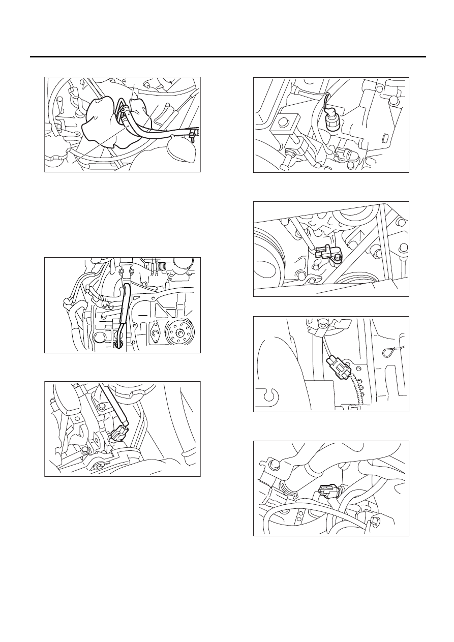
4) Connect the connector to the camshaft position
sensor.

5) Connect the connector to the oil pressure switch.

6) Connect the connector to the crankshaft position
sensor.

7) Connect the knock sensor connector.

8) Connect the connectors to the engine coolant
temperature sensor.

(A) Fuel delivery hose

(B) Return hose

(C) Evaporation hose

FU-00259

( A )

( B )

( C )

FU-00148

FU-00147

FU-00146

FU-00056

FU-00062

FU-00145

FU(H4SO)-19

FUEL INJECTION (FUEL SYSTEMS)

INTAKE MANIFOLD

9) Install the air cleaner case stay RH and engine
harness bracket, and connect the engine harness
connectors to the bulkhead connectors.

10) Connect the brake booster hose.

11) Connect the engine coolant hose (A) to the
throttle body.

12) Connect the PCV hose to the intake manifold.

13) Connect the spark plug cords to the spark
plugs.

14) Install the power steering pump and reservoir
tank to bracket.

(1) Install the reservoir tank to bracket.

(2) Connect the connector to the power steering
pump switch.

(3) Tighten the bolts which install power steer-
ing pump bracket.

Tightening torque:

22 N·m (2.2 kgf-m, 15.9 ft-lb)

(4) Install the power steering pipes onto the
right side intake manifold protector.

FU-00258

FU-00143

FU-00361

(A)

(A)

FU-00141

FU-00020

FU-00017

FU-00139

FU-00255

FU(H4SO)-20

FUEL INJECTION (FUEL SYSTEMS)

INTAKE MANIFOLD

(5) Install the front side V-belt. <Ref. to
ME(H4SO)-42, INSTALLATION, V-belt.>
(6) Install the resonator chamber.

Tightening torque:

33 N·m (3.4 kgf-m, 24.6 ft-lb)

15) Connect the accelerator cable (A). <Ref. to
SP(H4SO)-10, INSTALLATION, Accelerator Con-
trol Cable.>
16) Connect the cruise control cable (B). (With
cruise control models)

17) Install the air intake duct and air cleaner case.
<Ref. to IN(H4SO)-7, INSTALLATION, Air Intake
Duct.>
 and <Ref. to IN(H4SO)-6, INSTALLATION,
Air Cleaner Case.>
18) Connect the connector to the fuel pump relay.

19) Connect the battery ground cable to battery.

C: DISASSEMBLY

1) Disconnect the engine ground terminal from the
intake manifold.

2) Disconnect the connector from the ignition coil
and ignitor assembly.

3) Remove the ignition coil and ignitor assembly.

4) Remove the throttle body. <Ref. to FU(H4SO)-
14, REMOVAL, Throttle Body.>
5) Remove the EGR valve. <Ref. to FU(H4SO)-35,
REMOVAL, EGR Valve.>

FU-00261

FU-00251

(B)

(A)

FU-00431

FU-00009

FU-00263

FU-00264

FU-00286

FU(H4SO)-21

FUEL INJECTION (FUEL SYSTEMS)

INTAKE MANIFOLD

6) Disconnect the pressure regulator vacuum hose
from the intake manifold.

7) Remove the fuel pipe protector LH.

8) Remove the fuel pipe protector RH.

9) Disconnect the connectors from the fuel injec-
tors.

10) Disconnect the connector from the purge con-
trol solenoid valve.

11) Disconnect the air by-pass hose from the purge
control solenoid valve.
12) Remove the harness bands (A) and harness
bracket (B) which hold engine harness onto the in-
take manifold.

13) Remove the engine harness from the intake
manifold.
14) Remove the purge control solenoid valve.

FU-00265

FU-00266

FU-00267

FU-00268

FU-00269

FU-00517

(B)

(A)

(A)

(A)

FU-00271


Content   ..  27  28  29  30   ..