Subaru Impreza 3 / Impreza WRX / Impreza WRX STI. Manual - part 777
LAN(diag)-17
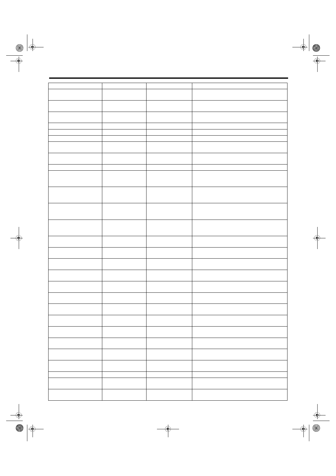
Subaru Select Monitor
LAN SYSTEM (DIAGNOSTICS)
Blower fan information
ON/OFF
CAN data input value
ON when blower fan is operating (always OFF for
auto A/C equipped models)
Smart judging flag
Smart System/Other
than Smart System
CAN data output value
Smart when integrated unit judges as a model
with Smart
Diesel judging flag
Diesel/Other than
Diesel
CAN data output value Display diesel/other than diesel
Turbo judging flag
Without turbo/TURBO CAN data output value Display engine equipped
AT type judging flag
4AT/5AT
CAN data output value Display transmission equipped
CVT judging flag
CVT/Other than CVT
CAN data output value Display CVT judging
Center display failure
OK/NG
CAN data input value
NG when there is a center display failure
Reception from center display (NAVI monitor)
NAVI Failure
OK/NG
CAN data input value
NG when there is a navigation system failure
Reception from Center Display
IE Bus failure
Can not use
CAN data input value
Reception from Center Display
Auto A/C failure
OK/NG
CAN data input value
NG when there is a failure in auto air conditioning
system
Reception from auto A/C module
EBD Warning Light
ON/OFF
CAN data input value
OK when EBD warning light is illuminated
Reception from VDC/ABS and transmission to
combination meter
ABS Warning Light
ON/OFF
CAN data input value
OK when ABS warning light is illuminated
Reception from VDC/ABS and transmission to
combination meter
VDC OFF flag
ON/OFF
CAN data input value
Vehicle dynamics control OFF SW is ON
Reception from VDC/ABS and transmission to
combination meter
VDC/ABS OK B
OK/NG
CAN data input value
NG when there is an error in VDC/ABS system
Reception from VDC/ABS
Lighting I Switch Input
ON/OFF
Body integrated unit
input value
ON when lighting switch illumination is ON
Lighting II Switch Input
ON/OFF
Body integrated unit
input value
ON when lighting switch headlight is ON
Dimmer Hi Switch Input
ON/OFF
Body integrated unit
input value
ON when dimmer switch is Hi beam position
Dimmer Pass Switch Input
ON/OFF
Body integrated unit
input value
ON when dimmer switch is passing position
Lighting I Lamp Output
ON/OFF
Body integrated unit
output value
ON when small light is illuminated
Lighting II Lamp Output
ON/OFF
Body integrated unit
output value
ON when headlight is illuminated
Lighting Hi Lamp Output
ON/OFF
Body integrated unit
output value
ON when Hi beam is illuminated
Front Fog Lamp Output
ON/OFF
Body integrated unit
output value
ON when front fog light is ON.
DRL Cancel Output
ON/OFF
Body integrated unit
output value
ON when lighting switch is “Headlight ON” and
dimmer switch is “Hi beam” or “Passing” position
Power Supply Tr
ON/OFF
Body integrated unit
output value
ON when lighting switch is “Head” position without
inserting key in key cylinder
Spot map lamp output
ON/OFF
Body integrated unit
output value
ON when one of the doors is open (except for tail
gate)
Eco switch information
ON/OFF
CAN data output value Not applicable
Off delay time
OFF, Short, Normal,
Long
Body integrated unit
setting items
Customize setting
Check engine warning
lamp output
ON, OFF, Blink 1,
Blink 2, Blink 3
Body integrated unit
output value
Warning light is activated
Items to be displayed
Unit of measure
Remarks
Note