Subaru Impreza 3 / Impreza WRX / Impreza WRX STI. Manual - part 755


  Index      Subaru     Subaru Impreza 3 / Impreza WRX / Impreza WRX STI - service repair manual 2008-2014 year


Search            


Content   ..  753  754  755  756   ..


Subaru Impreza 3 / Impreza WRX / Impreza WRX STI. Manual - part 755


EB-31

Rear Gate

EXTERIOR BODY PANELS

2. REAR GATE DAMPER STAY

CAUTION:

• Do not damage piston rods and oil seals.

• Never  disassemble  cylinders:  They  contain

gas.

• Rear gate panels are heavy. When removing

and installing them, always work in a team of

two or more persons.

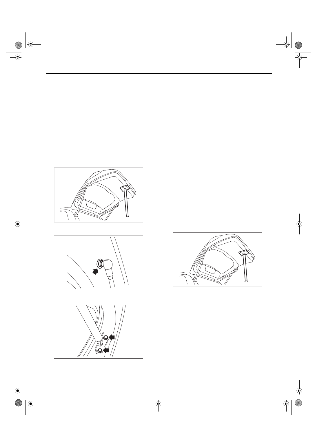
1) Before removing the rear gate damper stay, pre-

vent  the  rear  gate  from  closing  using  prop  or  the

like.
CAUTION:

If the prop comes off, operators may get injured

and  vehicle  may  get  damaged.  Make  sure  to

support  the  rear  gate  with  secure  material  to

prevent injury or damage.

2) Remove the mounting bolt of rear gate damper

stay.

3) Remove mounting bolt, and remove the damper

stay.

B: INSTALLATION

1. REAR GATE PANEL

CAUTION:

Rear  gate  panels  are  heavy.  When  removing

and installing them, always work in a team of

two or more persons.

1) Install each part in the reverse order of removal.
Tightening torque:

25 N·m (2.55 kgf-m, 18.4 ft-lb)

2) Install while paying attention to make a uniform

clearance around the rear gate panel. For the di-

mension of clearance, refer to “SPECIFICATION”

in “General Description”. <Ref. to EB-2, SPECIFI-

CATION, General Description.>

2. REAR GATE DAMPER STAY

CAUTION:

Rear  gate  panels  are  heavy.  When  removing

and installing them, always work in a team of

two or more persons.

1) Prevent the rear gate from closing using prop or

the like.
CAUTION:

If the prop comes off, operators may get injured

and  vehicle  may  get  damaged.  Make  sure  to

support  the  rear  gate  with  secure  material  to

prevent injury or damage.

2) Install each part in the reverse order of removal.
Tightening torque:

Refer to “COMPONENT” of “General Descrip-

tion”. <Ref. to EB-12, REAR GATE, COMPO-

NENT, General Description.>

EB-00389

EB-00282

EB-00382

EB-00389

EB-32

Rear Gate

EXTERIOR BODY PANELS

C: ADJUSTMENT

For  the  dimension  of  panel  around  the  rear  gate

panel, refer to “SPECIFICATION” in “General De-

scription”. <Ref. to EB-2, SPECIFICATION, Gener-

al Description.>

1) Align the rear gate panel longitudinal and lateral

position.

(1) Loosen the hinge attaching bolts.

(2) Align  the  rear  gate  panel  longitudinal  and

lateral panel dimension.

2) Adjust  the  gap  between  rear  gate  panel  and

body surface.

(1) Loosen the bolt.

(2) Tap  striker  using  plastic  hammer  to  adjust

the gap between rear gate panel and body sur-

face.

D: DISPOSAL

1. REAR GATE DAMPER STAY

CAUTION:

Gas is colorless, odorless, and harmless. How-

ever, gas pressure may spray cutting powder or

oil. Be sure to wear dust-resistant goggles.

1) Cover with a vinyl sack as shown in the figure.

NOTE:

Prevent  the  vinyl  sack  from  being  caught  by  drill

cutting edge.

2) Lift  the  body  side  slightly  with  piston  rods  fully

extended, and secure the body side with vise.

Drill a hole of 2 to 3 mm (0.08 to 0.12 in) diameter

at a point 10 to 200 mm (0.39 to 7.87 in) from the

body side, and bleed the gas in the rear gate damp-

er stay completely.

EB-00023

EB-00480

(1) Rear gate damper stay
(2) Vinyl sack

(1) Door side
(2) Body side
(3) 190 mm (7.48 in)
(4) 10 mm (0.39 in)
(5) Piston rod
(6) Cylinder
(7) Portion to be drilled

EB-00031

(1)

(2)

EB-00032

(3)

(4)

(1)

(5)

(6)

(7)

(2)

EB-33

Trunk Lid

EXTERIOR BODY PANELS

11.Trunk Lid

A: REMOVAL

1. TORSION BAR

1) Open the trunk lid.

2) Using the ST, remove the torsion bar from the

hinge link.
CAUTION:

During removal and installation, handle the tor-

sion bar carefully, because it will generate reac-

tive force.
Preparation tool: REMOVER (927780000)

3) Remove the torsion bars RH/LH.

2. TRUNK LID ARM

1) Disconnect the ground cable from battery.

2) Open the trunk lid to remove the trunk room trim.

<Ref. to EI-63, REMOVAL, Trunk Room Trim.>

3) Disconnect the trunk lid release cable. <Ref. to

SL-38,  REMOVAL,  Trunk  Lid  Latch  and  Actuator

Assembly.>

4) Disconnect the connectors, and remove the har-

ness clip, etc.

5) Remove the trunk lid mounting bolts, to remove

the trunk lid panel from the trunk lid arm.

6) Remove the torsion bar from the trunk lid hinge

link. <Ref. to EB-33, TORSION BAR, REMOVAL,

Trunk Lid.>

7) Remove the rear shelf trim. <Ref. to EI-62, RE-

MOVAL, Rear Shelf Trim.>

8) Remove the bolts, then remove the trunk lid arm.

3. TRUNK LID PANEL

1) Disconnect the ground cable from battery.

2) Disconnect the connector to remove the trunk lid

harness.

3) Detach the rear spoiler.

• Small  type:  <Ref.  to  EI-42,  SMALL  TYPE,  RE-

MOVAL, Rear Spoiler.>

• Large type: <Ref. to EI-42, LARGE TYPE, RE-

MOVAL, Rear Spoiler.>
CAUTION:

The trunk panel become lighter after removing

the  rear  spoiler,  so  be  careful  when  opening/

closing the trunk lid.

4) Remove the trunk lid latch and actuator assem-

bly.  <Ref.  to  SL-38,  REMOVAL,  Trunk  Lid  Latch

and Actuator Assembly.>

5) Remove  the  trunk  lid  garnish.  <Ref.  to  EI-73,

REMOVAL, Trunk Lid Garnish.>

6) Remove the bolts, then remove the trunk lid pan-

el from the trunk lid arm.

ST

EB-00067

EB-00066

EB-00157

EB-00066

EB-34

Trunk Lid

EXTERIOR BODY PANELS

B: INSTALLATION

1) Install each part in the reverse order of removal.
CAUTION:

Make sure that the harness grommet for the li-

cense plate light is securely installed on the ve-

hicle. If not properly installed, this may cause

water leakage.

2) Apply grease to the rotating area of hinges and

the torsion bar.

3) Install while paying attention to make a uniform

clearance  around  the  trunk  lid  panel.  For  the  di-

mension of clearance, refer to “SPECIFICATION”

in “General Description”. <Ref. to EB-2, SPECIFI-

CATION, General Description.>
Tightening torque:

Refer to “COMPONENT” of “General Descrip-

tion”. <Ref. to EB-13, TRUNK LID PANEL, 

COMPONENT, General Description.>

C: ADJUSTMENT

For  the  dimension  of  panel  around  the  trunk  lid

panel, refer to “SPECIFICATION” in “General De-

scription”. <Ref. to EB-2, SPECIFICATION, Gener-

al Description.>

1) Adjust the trunk lid panel lateral position.

(1) Loosen the mounting bolt.

(2) Align the trunk lid panel lateral panel dimen-

sion.

2) Adjust the gap between trunk lid panel and body

surface.

(1) Loosen the bolt.

(2) Tap striker using plastic hammer to adjust the

gap between trunk lid panel and body surface.

EB-00066

EB-00488


Content   ..  753  754  755  756   ..