Subaru Impreza 3 / Impreza WRX / Impreza WRX STI. Manual - part 705


  Index      Subaru     Subaru Impreza 3 / Impreza WRX / Impreza WRX STI - service repair manual 2008-2014 year


Search            


Content   ..  703  704  705  706   ..


Subaru Impreza 3 / Impreza WRX / Impreza WRX STI. Manual - part 705


IDI-11

Combination Meter System

INSTRUMENTATION/DRIVER INFO

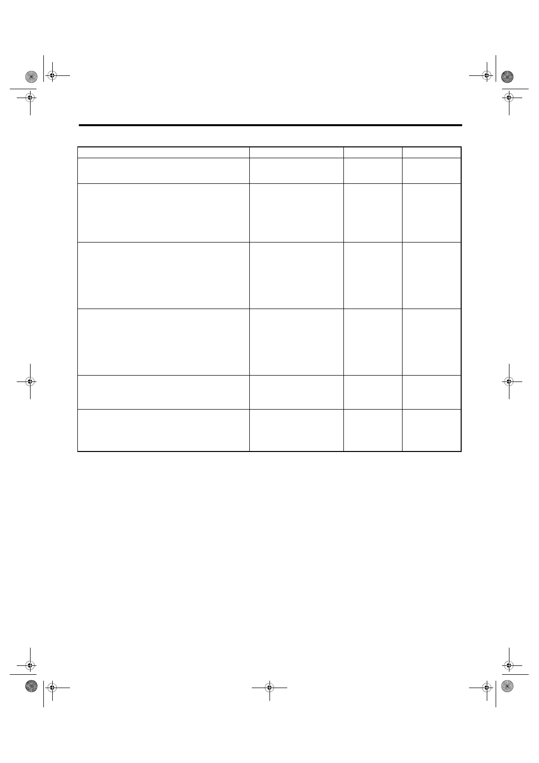
8. CHECK KEY WARNING SWITCH ALARM

Step

Check

Yes

No

1

CHECK KEY WARNING SWITCH ALARM.
1) Insert the key into ignition key lock.
2) Open the driver’s side door.

Does the buzzer sound from 
the meter?

Normal

Go to step 

2.

2

CHECK COMMUNICATION STATUS.
1) Prepare the Subaru Select Monitor.
2) On «System Selection Menu» display, 
select {Integ. unit mode}.
3) On {Current Data Display & Save}, select 
{Key-lock warning SW}.
4) Insert and remove the key.

Does the display change 
between ON ←→ OFF?

Go to step 

3.

Check the ignition 
switch circuit. 
<Ref. to SL-42, 
INSPECTION, 
Ignition Key Lock.>

3

CHECK COMMUNICATION STATUS.
1) On {Current Data Display & Save}, select 
{Driver’s door SW input}.
2) Open and close the door.

Does the display change 
between ON ←→ OFF?

Go to step 

4.

Check the door 
switch circuit. 
<Ref. to SL-19, 
CHECK DOOR 
SWITCH, 
INSPECTION, 
Keyless Entry Sys-
tem.>

4

CHECK DIAGNOSTIC TROUBLE CODE 
(DTC).
1) Turn the ignition switch to ON (engine OFF) 
and run the “PC application for Subaru Select 
Monitor”.
2) On «System Selection Menu» display, 
select {Integ. unit mode}.
3) Select the {Diagnostic Code(s) Display}.

Is DTC being displayed?

Perform the diag-
nosis according to 
DTC. <Ref. to 
LAN(diag)-32, 
LIST, List of Diag-
nostic Trouble 
Code (DTC).>

Go to step 

5.

5

CHECK COMBINATION METER.
Perform the self-diagnosis of combination 
meter. <Ref. to IDI-5, SELF-DIAGNOSIS, 
INSPECTION, Combination Meter System.>

Did the buzzer sound?

Go to step 

6.

Replace the meter 
case assembly.

6

CHECK COMBINATION METER.
1) Remove the combination meter.
2) Attach the buzzer to another vehicle on 
which the buzzer operates normally to check its 
operation.

Did the buzzer sound?

Replace the body 
integrated unit. 
<Ref. to SL-48, 
Body Integrated 
Unit.>

Replace the meter 
case assembly.

IDI-12

Combination Meter System

INSTRUMENTATION/DRIVER INFO

9. DTC DISPLAY MODE

The combination meter DTC can be displayed according to the following procedure.
CAUTION:

Perform the steps described in 2) through 4) within 10 seconds.

1) Within 3 seconds after turning the ignition switch to ON, set the lighting switch to tail light or headlight po-

sition.

2) Press the odo/trip meter knob four times.

3) Turn the lighting switch to OFF, and press the odo/trip meter knob four times.

4) Set the lighting switch to tail light or headlight position again, and press the odo/trip meter knob four times.

5) Go to “DTC display mode”.

When the DTC display mode operates, the display is changed every 3 seconds or {ECM}, {TCM}, {ABS/VDC}

is displayed cyclically in this order for every press of the trip knob. DTC is displayed in the following table ac-

cording to type of control module, receiving DTC, DTC detected or No DTC.

NOTE:

• When the engine starts during diagnosis, the self-diagnosis function is not cancelled, however, once igni-

tion switch is turned OFF or the vehicle is driven, the DTC display mode is cancelled automatically for safety.

• When the DTC of individual control modules changes in status from current trouble to past trouble, and the

trouble is fixed, the DTC will no longer appear in the combination meter if the engine is started three times

or more. In this case, read the DTC using the Subaru Select Monitor.

• Because the MT model is not equipped with a TCM, only “Receiving DTC” is displayed.

C: NOTE

For procedure of each component in the combination meter system, refer to the respective section.

• Combination meter: <Ref. to IDI-16, Combination Meter.>

• Speedometer: <Ref. to IDI-17, Speedometer.>

• Tachometer: <Ref. to IDI-18, Tachometer.>

• Fuel gauge: <Ref. to IDI-19, Fuel Gauge.>

• Engine coolant temperature gauge: <Ref. to IDI-20, Engine Coolant Temperature Gauge.>

Control module

Condition

Display

ECM

Receiving DTC

Trip “A” + “P (Blink)”

DTC detected

Trip “A” + “P xxxx”

No DTC

Trip “A” + “P ----”

TCM

Receiving DTC

Trip “B” + “P (Blink)”

DTC detected

Trip “B” + “P xxxx”

No DTC

Trip “B” + “P ----”

ABS/VDCCM

Receiving DTC

Trip “A” + “C (Blink)”

DTC detected

Trip “A” + “C xxxx”

No DTC

Trip “A” + “C ----”

When CAN communication error 
is occurred

 — 

“ ----- ”

IDI-13

Clock System

INSTRUMENTATION/DRIVER INFO

3. Clock System

A: WIRING DIAGRAM

Refer to “Clock System” in WI section. <Ref. to WI-147, WIRING DIAGRAM, Clock System.>

B: INSPECTION

1. SYMPTOM CHART

2. CHECK POWER SUPPLY AND GROUND CIRCUIT AND COMMUNICATION CIRCUIT

Symptoms

Repair order

Index

No display is shown.

1. Power supply
2. Ground circuit
3. Communication circuit harness
4. Clock body

<Ref. to IDI-13, CHECK POWER SUPPLY AND 
GROUND CIRCUIT AND COMMUNICATION CIR-
CUIT, INSPECTION, Clock System.>

Ambient air temperature/fuel 
economy displays do not appear.

1. Power supply
2. Ground circuit
3. Communication circuit harness
4. Clock body

<Ref. to IDI-14, CHECK CLOCK SYSTEM COMMU-
NICATION CIRCUIT, INSPECTION, Clock System.>

Only ambient air temperature dis-
play is not displayed.

1. Power supply
2. Harness
3. Ambient sensor
4. Communication circuit
5. Clock body

<Ref. to IDI-14, CHECK AMBIENT TEMPERATURE 
METER SYSTEM COMMUNICATION CIRCUIT, 
INSPECTION, Clock System.>

Only fuel economy display is not 
displayed.

1. Setting
2. Communication circuit
3. Clock body

<Ref. to IDI-15, CHECK COMMUNICATION CIRCUIT 
OF FUEL ECONOMY SYSTEM, INSPECTION, Clock 
System.>

Step

Check

Yes

No

1

CHECK POWER SUPPLY.
1) Disconnect the clock connector.
2) Measure the voltage between clock connec-
tor and chassis ground.

Connector & terminal

(i59) No. 10 (+) — Chassis ground (–):

Is the voltage 10 V or more?

Go to step 

2.

Check the harness 
for a open or short 
between the fuse 
and clock.

2

CHECK GROUND CIRCUIT.
Measure the resistance between the clock con-
nector and chassis ground.

Connector & terminal

(i59) No. 6 — Chassis ground:

Is the resistance less than 10 

Ω?

Go to step 

3.

Repair or replace 
the harness.

3

CHECK HARNESS BETWEEN CLOCK AND 
COMBINATION METER.
1) Disconnect the combination meter connec-
tor.
2) Measure the resistance between the clock 
connector and combination meter connector.

Connector & terminal

(i59) No. 5 — (i10) No. 29:

Is the resistance less than 10 

Ω?

Go to step 

4.

Repair or replace 
the harness.

4

CHECK CLOCK.
1) Remove the clock.
2) Attach the clock to another vehicle on which 
the clock operates normally to check its opera-
tion.

Is clock normal?

Replace the meter 
case assembly.

Replace the clock 
body.

IDI-14

Clock System

INSTRUMENTATION/DRIVER INFO

3. CHECK CLOCK SYSTEM COMMUNICATION CIRCUIT

4. CHECK AMBIENT TEMPERATURE METER SYSTEM COMMUNICATION CIRCUIT

Step

Check

Yes

No

1

CHECK POWER SUPPLY.
1) Disconnect the clock connector.
2) Measure the voltage between clock connec-
tor and chassis ground.

Connector & terminal

(i59) No. 8 (+) — Chassis ground (–):

Is the voltage 10 V or more?

Go to step 

2.

Repair or replace 
the harness.

2

CHECK GROUND CIRCUIT.
Measure the resistance between the clock con-
nector and chassis ground.

Connector & terminal

(i59) No. 6 — Chassis ground:

Is the resistance less than 10 

Ω?

Go to step 

3.

Repair or replace 
the harness.

3

CHECK HARNESS BETWEEN CLOCK AND 
COMBINATION METER.
1) Disconnect the combination meter connec-
tor.
2) Measure the resistance between the clock 
connector and combination meter connector.

Connector & terminal

(i59) No. 5 — (i10) No. 29:

Is the resistance less than 10 

Ω?

Go to step 

4.

Repair or replace 
the harness.

4

CHECK CLOCK.
1) Remove the clock.
2) Attach the clock to another vehicle on which 
the clock operates normally to check its opera-
tion.

Is clock normal?

Replace the meter 
case assembly.

Replace the clock 
body.

Step

Check

Yes

No

1

CHECK AMBIENT SENSOR POWER SUP-
PLY.
1) Disconnect the ambient sensor connector.
2) Turn the ignition switch to ON.
3) Measure the voltage between the ambient 
sensor connector and chassis ground.

Connector & terminal

(F78) No. 2 (+) — Chassis ground (–):

Is the voltage 4 V or more?

Go to step 

2.

Check the harness 
for a open or short 
between the fuse 
and clock.

2

CHECK HARNESS BETWEEN AMBIENT 
SENSOR AND COMBINATION METER.
1) Disconnect the combination meter connec-
tor.
2) Measure the resistance between the ambi-
ent sensor connector and the combination 
meter connector.

Connector & terminal

(F78) No. 1 — (i10) No. 23:
(F78) No. 2 — (i10) No. 24:

Is the resistance less than 10 

Ω?

Go to step 

3.

Repair or replace 
the harness.

3

CHECK AMBIENT SENSOR.
1) Remove the ambient sensor. <Ref. to AC-
44, REMOVAL, Ambient Sensor (Auto A/C 
Model).>
2) Check the ambient sensor. <Ref. to 
AC(diag)-29, AMBIENT SENSOR, Diagnostic 
Procedure for Sensors.>

Is the ambient sensor operating 
properly?

Go to step 

4.

Replace the ambi-
ent sensor.


Content   ..  703  704  705  706   ..