Subaru Impreza 3 / Impreza WRX / Impreza WRX STI. Manual - part 704
IDI-7
Combination Meter System
INSTRUMENTATION/DRIVER INFO
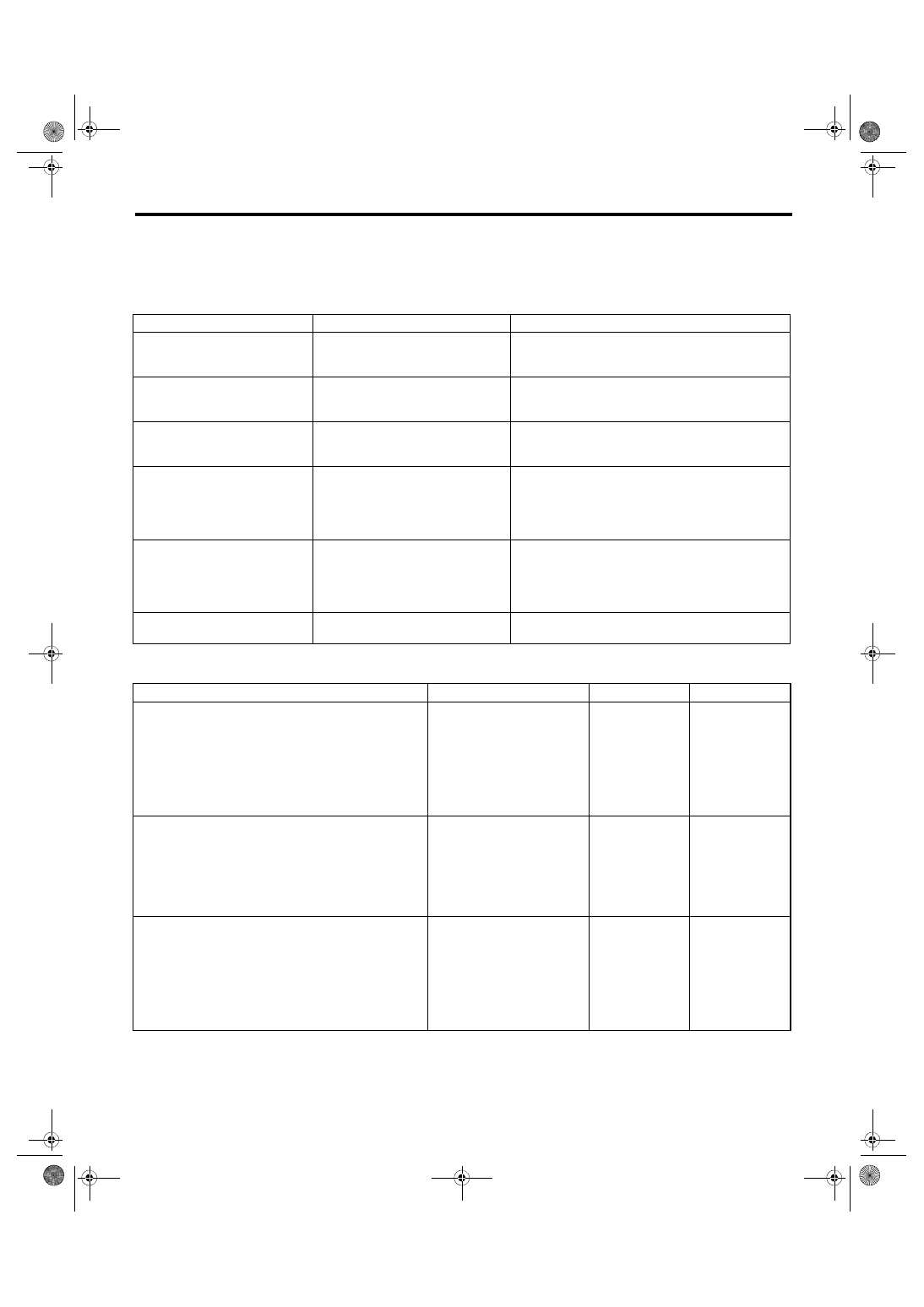
2. SYMPTOM CHART
CAUTION:
When measuring the voltage and resistance of each control module or sensor, use a tapered pin with
a diameter of less than 0.64 mm (0.025 in) in order to avoid poor contact. Do not insert the pin more
than 2 mm (0.08 in).
3. CHECK POWER SUPPLY AND GROUND CIRCUIT
Symptoms
Repair order
Note
Combination meter assembly
does not operate.
1. Power supply
2. Ground circuit
3. Combination meter
<Ref. to IDI-7, CHECK POWER SUPPLY AND
GROUND CIRCUIT, INSPECTION, Combination
Meter System.>
Speedometer does not operate.
1. VDC C/M
2. Harness
3. Combination meter
<Ref. to IDI-8, CHECK VDC CONTROL MODULE,
INSPECTION, Combination Meter System.>
Tachometer does not operate.
1. ECM
2. Harness
3. Combination meter
<Ref. to IDI-8, CHECK ENGINE CONTROL MODULE
(ECM), INSPECTION, Combination Meter System.>
Fuel gauge does not operate.
1. Communication circuit
2. Harness
3. Body integrated unit
4. Fuel level sensor
5. Combination meter
<Ref. to IDI-8, CHECK FUEL LEVEL SENSOR,
INSPECTION, Combination Meter System.>
Engine coolant temperature
gauge does not operate.
1. Communication circuit
2. Engine coolant temperature sen-
sor
3. Harness
4. Combination meter
<Ref. to IDI-10, CHECK ENGINE COOLANT TEM-
PERATURE SENSOR, INSPECTION, Combination
Meter System.>
Warning buzzer for key left in igni-
tion does not sound.
1. Communication circuit
2. Combination meter
<Ref. to IDI-11, CHECK KEY WARNING SWITCH
ALARM, INSPECTION, Combination Meter System.>
Step
Check
Yes
No
1
CHECK POWER SUPPLY FOR COMBINA-
TION METER.
1) Remove the combination meter. <Ref. to
IDI-16, REMOVAL, Combination Meter.>
2) Measure the voltage between combination
meter connector and chassis ground.
Connector & terminal
(i10) No. 1 (+) — Chassis ground (–):
Is the voltage 10 V or more?
Check the harness
for open or short
between the fuse
and combination
meter.
2
CHECK POWER SUPPLY FOR COMBINA-
TION METER.
1) Turn the ignition switch to ON.
2) Measure the voltage between combination
meter connector and chassis ground.
Connector & terminal
(i10) No. 2 (+) — Chassis ground (–):
Is the voltage 10 V or more?
Check the harness
for open or short
between the igni-
tion switch and
combination meter.
3
CHECK GROUND CIRCUIT OF COMBINA-
TION METER.
1) Turn the ignition switch to OFF.
2) Measure the resistance of harness between
combination meter connector and body ground.
Connector & terminal
(i10) No. 21 — Chassis ground:
(i10) No. 22 — Chassis ground:
Is the resistance less than 10
Ω?
Replace the meter
case assembly.
Repair or replace
the harness.