Subaru Impreza 3 / Impreza WRX / Impreza WRX STI. Manual - part 682


  Index      Subaru     Subaru Impreza 3 / Impreza WRX / Impreza WRX STI - service repair manual 2008-2014 year


Search            


Content   ..  680  681  682  683   ..


Subaru Impreza 3 / Impreza WRX / Impreza WRX STI. Manual - part 682


WW-9

Combination Switch (Wiper)

WIPER AND WASHER SYSTEMS

2. REAR WIPER

1) Check with Subaru Select Monitor
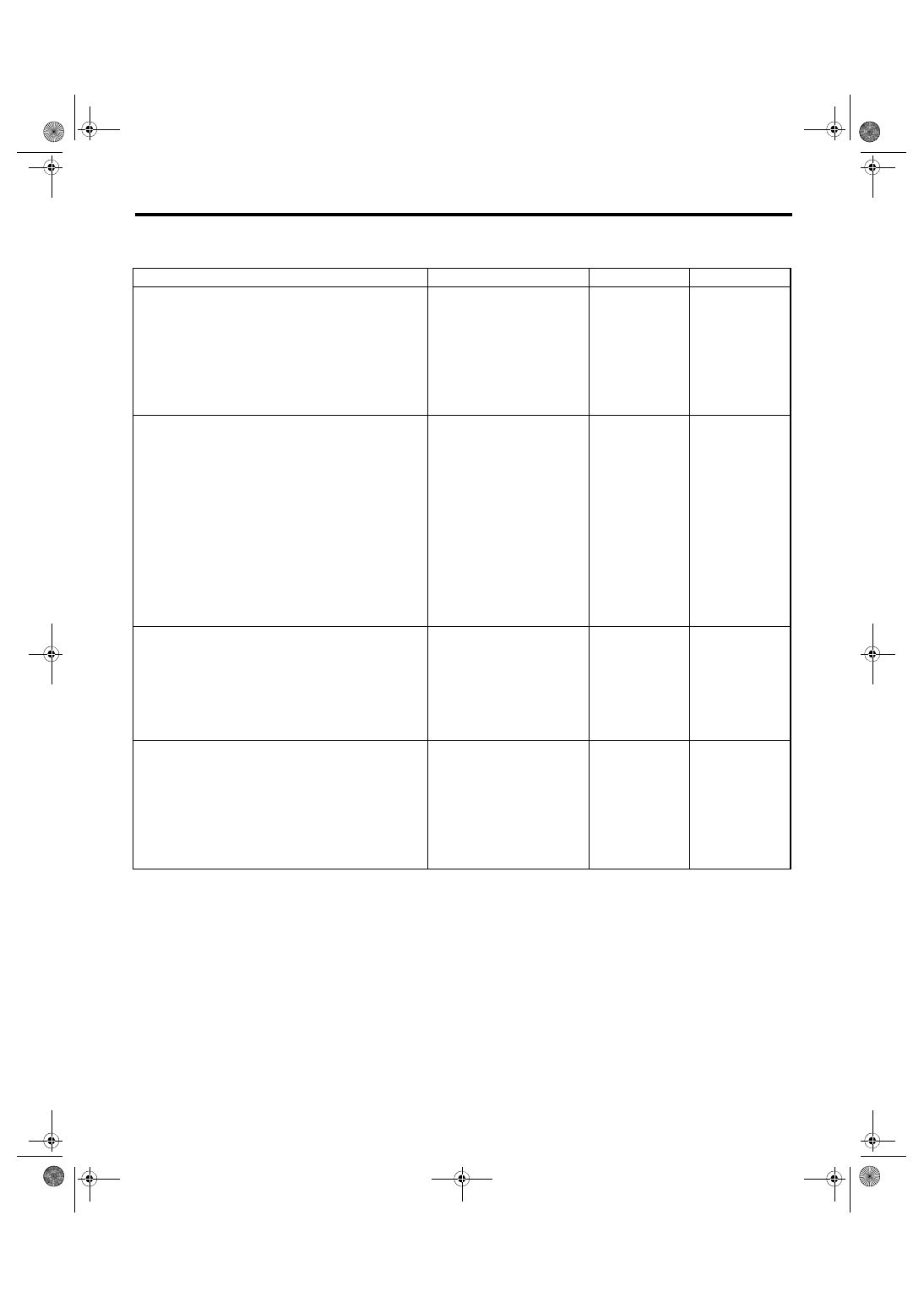
Step

Check

Yes

No

1

CHECK INPUT OF REAR WIPER SWITCH.
Check the input from body integrated unit using 
the Subaru Select Monitor.
1) Prepare the Subaru Select Monitor kit.
2) Turn the ignition switch to ON.
3) On «System Selection Menu» display, 
select {Integ. unit mode}.
4) Select {Current Data Display & Save}.
5) Check the input of the rear wiper switch.

Is the input normal?

Go to step 

4.

Go to step 

2.

2

CHECK HARNESS.
1) Turn the ignition switch to OFF, disconnect 
the ground cable from battery.
2) Disconnect the connector of body inte-
grated unit.
3) Disconnect the connector from wiper 
switch.
4) Measure the resistance between body inte-
grated unit and wiper switch, and between 
wiper switch and chassis ground.

Connector & terminal

(B281) No. 18 — (B70) No. 10:
(B281) No. 27 — (B70) No. 13:
(B281) No. 28 — (B70) No. 12:
(B70) No. 8 — Chassis ground:

Is the resistance less than 10 

Ω?

Go to step 

3.

Repair the harness 
between body inte-
grated unit and 
wiper switch, and 
between wiper 
switch and chassis 
ground.

3

CHECK INPUT VOLTAGE OF BODY INTE-
GRATED UNIT.
1) Connect the ground cable to battery.
2) Turn the ignition switch to ACC.
3) Check the input voltage of body integrated 
unit.

Connector & terminal

(B280) No. 7 (+) — Chassis ground (–):

Is the voltage 10 V or more?

Go to step 

4.

Check the harness 
and fuse.

4

CHECK OUTPUT OF BODY INTEGRATED 
UNIT.
When the rear wiper switch is operated, check 
the output using the Subaru Select Monitor.
1) Turn the ignition switch to ON.
2) Operate the rear wiper switch and set to 
each position of ON and INT.
3) At this time, check the body integrated unit 
output.

When set to ON, is ON output 
continuous? When set to INT, is 
ON/OFF output repeated? (4 
door model: INT OFF time 
(when vehicle parked): 3 sec-
onds; 5 door model: INT OFF 
time (when vehicle parked): 12 
seconds)

Check the rear 
wiper motor circuit.

Replace the body 
integrated unit. 
<Ref. to SL-48, 
Body Integrated 
Unit.>

WW-10

Combination Switch (Wiper)

WIPER AND WASHER SYSTEMS

2) Check rear wiper motor circuit

Step

Check

Yes

No

1

CHECK POWER SUPPLY CIRCUIT OF THE 
REAR WIPER MOTOR.
1) Disconnect the harness connector of the 
rear wiper motor.
2) Turn the ignition switch to ACC.
3) Measure the voltage between the rear wiper 
motor harness connector terminal and chassis 
ground.

Connector & terminal

(D43) No. 3 (+) — Chassis ground (–):

Is the voltage 10 V or more?

Go to step 

2.

• Check the fuse 
(No. 23 in fuse & 
relay box).
• Check the fus-
ible link (No. 7 in 
main fuse box).

2

CHECK GROUND CIRCUIT OF REAR WIPER 
MOTOR.
1) Turn the ignition switch to OFF.
2) Measure the resistance between the rear 
wiper motor harness connector terminal and 
chassis ground.

Connector & terminal

(D43) No. 4 — Chassis ground:

Is the resistance less than 10 

Ω?

Go to step 

3.

Repair the open 
circuit of the rear 
wiper motor 
ground circuit.

3

CHECK HARNESS BETWEEN BODY INTE-
GRATED UNIT AND REAR WIPER MOTOR.
1) Turn the ignition switch to OFF.
2) Disconnect the harness connector of body 
integrated unit.
3) Disconnect the harness connector of the 
rear wiper motor.
4) Measure the resistance between the har-
ness connector terminals of the body integrated 
unit and rear wiper motor.

Connector & terminal

(B279) No. 8 — (D43) No. 1:
(B279) No. 9 — (D43) No. 2:

Is the resistance less than 10 

Ω?

Go to step 

4.

Repair the open 
circuit of the har-
ness between 
body integrated 
unit and rear wiper 
motor.

4

CHECK INPUT VOLTAGE OF BODY INTE-
GRATED UNIT.
1) Turn the ignition switch to ACC.
2) Check the input voltage of body integrated 
unit.

Connector & terminal

(B279) No. 21 (+) — Chassis ground (–):

Is the voltage 10 V or more?

Go to step 

5.

Check the harness 
and fuse.

5

CHECK OUTPUT OF BODY INTEGRATED 
UNIT.
1) Connect the harness connector of body 
integrated unit.
2) Disconnect the connector of the rear wiper 
motor.
3) Turn the ignition switch to ACC.
4) Measure the voltage between rear wiper 
motor connector and chassis ground.

Connector & terminal

(D43) No. 2 (+) — Chassis ground (–):

Is the voltage less than 1.5 V 
when the rear wiper switch is 
OFF, and is the voltage 10 V or 
more when the rear wiper 
switch is ON?

Go to step 

6.

Replace the body 
integrated unit. 
<Ref. to SL-48, 
Body Integrated 
Unit.>

6

CHECK OPERATION OF REAR WIPER MO-
TOR.
1) Remove the rear wiper motor.
2) Check the rear wiper motor. <Ref. to WW-
21, INSPECTION, Rear Wiper Motor.>

Does the rear wiper motor 
rotate normally?

End.

Replace the rear 
wiper motor.

WW-11

Wiper Blade

WIPER AND WASHER SYSTEMS

4. Wiper Blade

A: REMOVAL

1. FRONT

Type A

1) While  pushing  the  locking  clip  (A),  push  in  the

arm to the blade assembly side. (arrow mark 2)

2) Pull the arm while lifting the arm (arrow mark 3),

and then remove the blade assembly from the arm.
Type B

1) Pull up the locking clip (A) and then push the arm

to blade assembly side. (arrow mark 2)

2) Pull the arm while lifting the arm (arrow mark 3),

and then remove the blade assembly from the arm.

2. REAR

Turn the blade in the direction of arrow (A) and re-

move it from arm.

B: INSTALLATION

1) Install each part in the reverse order of removal.

2) Confirm that the clip is locked securely.

C: DISASSEMBLY

1. FRONT

Pull  side  (A)  of  the  wiper  rubber  stopper  and  re-

move the rubber from the blade assembly.

• Type A

• Type B

WW-00064

1

2

2

3

3

(A)

WW-00530

1

2

2

3

(A)

(A) Turn the wiper blade.


(1) Wiper arm
(2) Wiper blade
(3) Wiper blade attachment section

(1)

(2)

(3)

(A)

WW-00207

WW-00009

WW-00579

WW-12

Wiper Blade

WIPER AND WASHER SYSTEMS

2. REAR

Pull the wiper rubber top slightly from stopper (A)

and pull out completely.

D: ASSEMBLY

1. FRONT

1) Insert the wiper rubber onto the blade so that the

stopper is in the position shown in the figure.

2) Make sure the wiper rubber is securely fastened

to the pull stopper (A).

• Type A

• Type B

2. REAR

1) Insert the wiper rubber into claw (B).

2) Insert the wiper rubber until its top end protrudes

approx. 20 mm (0.79 in) from stopper (D).

3) Insert the wiper rubber into claw (A).

WW-00143

(A)

WW-00501

WW-00009

WW-00579

WW-00421

A

B

C

D

WW-00145

A

B

WW-00146

D

20 mm ( 0.79 in. )

A

WW-00147


Content   ..  680  681  682  683   ..