Subaru Impreza 3 / Impreza WRX / Impreza WRX STI. Manual - part 681
WW-5
General Description
WIPER AND WASHER SYSTEMS
D: PREPARATION TOOL
1. SPECIAL TOOL
2. GENERAL TOOL
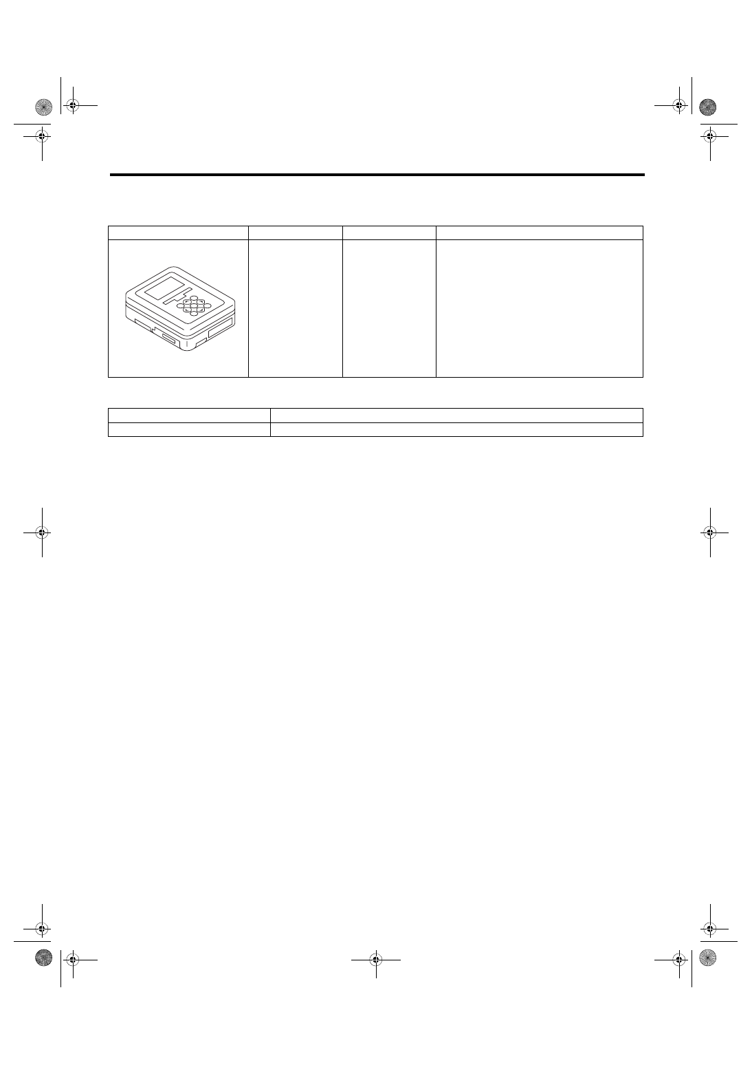
ILLUSTRATION
TOOL NUMBER
DESCRIPTION
REMARKS
1B022XU0
SUBARU SELECT
MONITOR III KIT
Used for setting of each function and trouble-
shooting for electrical system.
TOOL NAME
REMARKS
Circuit tester
Used for checking voltage and continuity.
ST1B022XU0