Subaru Impreza 3 / Impreza WRX / Impreza WRX STI. Manual - part 677


  Index      Subaru     Subaru Impreza 3 / Impreza WRX / Impreza WRX STI - service repair manual 2008-2014 year


Search            


Content   ..  675  676  677  678   ..


Subaru Impreza 3 / Impreza WRX / Impreza WRX STI. Manual - part 677


LI-31

License Plate Light

LIGHTING SYSTEM

25.License Plate Light
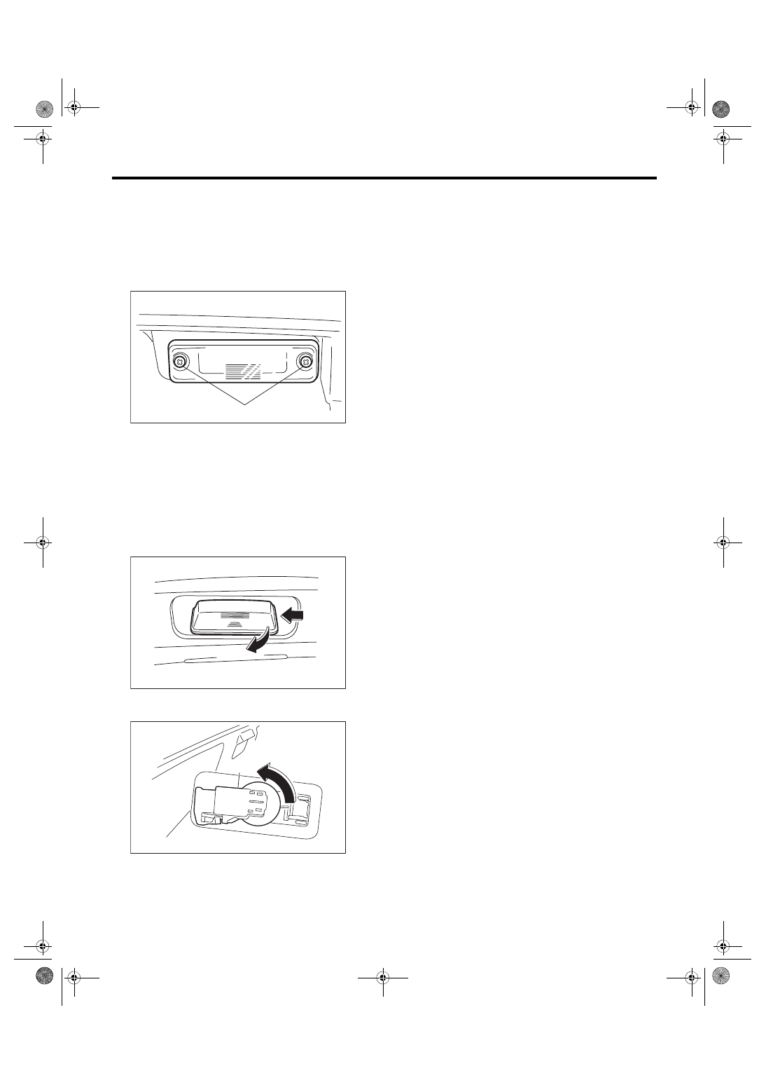
A: REMOVAL

1. 4 DOOR MODEL

1) Disconnect the ground cable from battery.

2) Remove the license plate light mounting screw

(A) and then remove the lens.

3) Remove the bulb.

4) Remove  the  trunk  lid  garnish.  <Ref.  to  EI-73,

REMOVAL, Trunk Lid Garnish.>

5) Remove  the  license  plate  light  assembly  har-

ness.

2. 5 DOOR MODEL

1) Disconnect the ground cable from battery.

2) Remove the license plate light while pushing it to

the left and pulling it.

3) Disconnect the harness connector, and remove

the socket (A).

4) Remove the bulb.

B: INSTALLATION

Install each part in the reverse order of removal.

C: INSPECTION

1) Visually check the bulb for blow out.

2) Check  the  bulb  specification.  <Ref.  to  LI-2,

SPECIFICATION, General Description.>

3) Replace the bulb if it is found defective.

LI-00034

(A)

LI-00821

LI-00939

(A)

LI-32

High-mounted Stop Light

LIGHTING SYSTEM

26.High-mounted Stop Light

A: REMOVAL

1. 4 DOOR MODEL (STANDARD TYPE)

1) Disconnect the ground cable from battery.

2) Disconnect the high-mounted stop light connec-

tor.

3) Loosen the bolt, and remove the high-mounted

stop light assembly.

4) Remove  the  high-mounted  stop light assembly

cover.

5) Turn the socket and remove the bulb.

2. 4 DOOR MODEL (WITH BUILT-IN REAR 

SPOILER)

1) Disconnect the ground cable from battery.

2) Detach the rear spoiler. <Ref. to EI-42, REMOV-

AL, Rear Spoiler.>

3) Remove the screw, and remove the high-mount-

ed stop light.

3. 5 DOOR MODEL

1) Disconnect the ground cable from battery.

2) Remove  the  roof  spoiler.  <Ref.  to  EI-41,  RE-

MOVAL, Roof Spoiler.>

3) Remove the caps and screws, then remove the

high-mounted stop light.

B: INSTALLATION

Install each part in the reverse order of removal.
Tightening torque:

4 door model (standard type)

7.5 N·m (0.76 kgf-m, 5.5 ft-lb)

C: INSPECTION

1. 4 DOOR MODEL (STANDARD TYPE)

1) Visually check the bulb for blow out.

2) Check  the  bulb  specification.  <Ref.  to  LI-2,

SPECIFICATION, General Description.>

3) Replace the bulb if it is found defective.

2. EXCEPT FOR 4 DOOR MODEL (STAN-

DARD TYPE)

1) Install the high-mounted stop light to test if it illu-

minates normally.

2) If it fails to illuminate normally, replace the high-

mounted stop light with a new part.
NOTE:

Since  LED  (Light  Emitting  Diode)  is  used  for  the

high-mounted stop light, replace the high-mounted

stop light assembly if the LED burns out.

LI-00221

LI-01142

LI-01151

LI-00858

LI-33

Spot Map Light

LIGHTING SYSTEM

27.Spot Map Light

A: REMOVAL

1) Disconnect the ground cable from battery.

2) Remove the lens (A) and spot map light mount-

ing screws (B).

• Model without sunroof

• Model with sunroof

3) Disconnect the harness connectors and remove

the spot map light.

4) Remove the bulb.

B: INSTALLATION

Install each part in the reverse order of removal.

C: INSPECTION

1. SPOT MAP LIGHT BULB

1) Visually check the bulb for blow out.

2) Check  the  bulb  specification.  <Ref.  to  LI-2,

SPECIFICATION, General Description.>

3) Replace the bulb if it is found defective.

2. SPOT MAP LIGHT SWITCH

1) Remove the spot map light.

2) Check the resistance of spot map light.

• Model without sunroof

• Model with sunroof

3) Replace the spot map light if the inspection re-

sult is not within the standard value.

(A)

LI-00224

(B)

LI-00225

SR-00222

(A)

SR-00223

(B)

Switch position

Terminal No.

Standard value

OFF

1 and 2

1 MΩ or more

ON

1 and 2

18±5.4 Ω

LI-01100

1

2

3

4

5

6

LI-00363

2 1

LI-34

Room Light

LIGHTING SYSTEM

28.Room Light

A: REMOVAL

1) Disconnect the ground cable from battery.

2) Remove  the  lens  (A)  and  room  light  mounting

screws (B).

3) Disconnect the harness connector and remove

the room light.

4) Remove the bulb.

B: INSTALLATION

Install each part in the reverse order of removal.

C: INSPECTION

1. ROOM LIGHT BULB

1) Visually check the bulb for blow out.

2) Check  the  bulb  specification.  <Ref.  to  LI-2,

SPECIFICATION, General Description.>

3) Replace the bulb if it is found defective.

2. ROOM LIGHT SWITCH

1) Remove the room light.

2) Measure  the  resistance  between  room  light

switch terminals.

3) Connect  terminal  No.  3  to  the  battery  positive

terminal and terminal No. 1 and No. 2 to the battery

ground terminal, and check room light operation.

4) Replace the room light if it is found defective.

LI-00315

(A)

LI-00316

(B)

Switch position

Terminal No.

Standard value

OFF

 — 

1 MΩ or more

ON

1 and 3

1.5±0.5 Ω

DOOR

2 and 3

1.5±0.5 Ω

Switch position

Light status

OFF

Light OFF

ON

Light ON

DOOR

Light ON

LI-00257

3 2 1


Content   ..  675  676  677  678   ..