Subaru Impreza 3 / Impreza WRX / Impreza WRX STI. Manual - part 614


  Index      Subaru     Subaru Impreza 3 / Impreza WRX / Impreza WRX STI - service repair manual 2008-2014 year


Search            


Content   ..  612  613  614  615   ..


Subaru Impreza 3 / Impreza WRX / Impreza WRX STI. Manual - part 614


AB-23

Side Airbag Sensor

AIRBAG SYSTEM

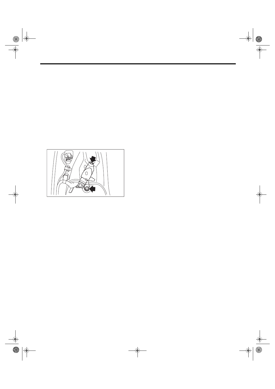
10.Side Airbag Sensor

A: REMOVAL

1) Turn the ignition switch to OFF.

2) Disconnect  the  ground  cable  from  battery  and

wait for at least 60 seconds before starting work.

3) Remove the front outer seat belt. <Ref. to SB-18,

OUTER  SEAT  BELT  ASSEMBLY,  REMOVAL,

Front Seat Belt.>

4) Remove the nuts and then remove the side air-

bag sensor.
CAUTION:

• Do not separate the side airbag sensor and

bracket.  It  cause  the  airbag  system  malfunc-

tion.

• If the sensor is removed from the bracket, be

sure to replace with a new part.

5) Disconnect the airbag connector.

B: INSTALLATION

CAUTION:

Do not reuse the bolt and nut.

Always  replace  with  the  specified  new  bolts

and nuts.

Install each part in the reverse order of removal.
Tightening torque:

7.5 N·m (0.76 kgf-m, 5.5 ft-lb)

C: INSPECTION

Check for the following, and replace the damaged

parts with new parts.

• The bracket or connector of side airbag sensor is

damaged.

• Side airbag has been activated.

AB-01835

AB-24

Curtain Airbag Sensor

AIRBAG SYSTEM

11.Curtain Airbag Sensor

A: REMOVAL

1) Turn the ignition switch to OFF.

2) Disconnect  the  ground  cable  from  battery  and

wait for at least 60 seconds before starting work.

3) Remove the rear seat. <Ref. to SE-13, REMOV-

AL, Rear Seat.>

4) Remove  the  nuts  and  then  remove  the  curtain

airbag sensor.

5) Disconnect the airbag connector.

B: INSTALLATION

CAUTION:

• Do not reuse the bolt and nut.

Always use new bolts and nuts for them.

• When installing the sensor, insert the set pin

on the backside of the sensor into the hole on

the body side securely.

Install in the reverse order of removal.
Tightening torque:

7.5 N·m (0.76 kgf-m, 5.5 ft-lb)

C: INSPECTION

Check for the following, and replace the damaged

parts with new parts.

• Curtain airbag sensor or connector is damaged.

• Curtain airbag has been activated.

AB-01754

AB-25

Satellite Safing Sensor

AIRBAG SYSTEM

12.Satellite Safing Sensor

A: REMOVAL

1) Turn the ignition switch to OFF.

2) Disconnect  the  ground  cable  from  battery  and

wait for at least 60 seconds before starting work.

3) Remove the rear seat cushion. <Ref. to SE-13,

REMOVAL, Rear Seat.>

4) Remove the satellite safing sensor cover.

5) Remove the nut, and remove the satellite safing

sensor.
CAUTION:

• Do  not  separate  the  satellite  safing  sensor

and  bracket.  It  cause  the  airbag  system  mal-

function.

• If the sensor is removed from the bracket, be

sure to replace with a new part.

6) Disconnect the airbag connector.

B: INSTALLATION

CAUTION:

• Do not reuse the bolt and nut.

Always  replace  with  the  specified  new  bolts

and nuts.

• When  installing  the  satellite  safing  sensor

cover, push the cover securely until it contacts

the floor panel.

• If  the  satellite  safing  sensor  cover  is  too

loose at its mounting portion to remove easily,

replace with a new satellite safing sensor cov-

er.

• After  installing  the  satellite  safing  sensor

cover, make sure that the sensor harness does

not get caught.

Install each part in the reverse order of removal.
Tightening torque:

7.5 N·m (0.76 kgf-m, 5.5 ft-lb)

C: INSPECTION

Check for the following, and replace the damaged

parts with new parts.

• Mounting bracket or connector of satellite safing

sensor is damaged.

• The satellite safing sensor cover is damaged

• Side airbag or curtain airbag has been activated.

AB-01847

AB-01846

AB-26

Roll Connector

AIRBAG SYSTEM

13.Roll Connector

A: REMOVAL

1) Turn the ignition switch to OFF.

2) Disconnect  the  ground  cable  from  battery  and

wait for at least 60 seconds before starting work.

3) Remove the driver’s airbag module. <Ref. to AB-

15, Driver’s Airbag Module.>

4) Remove the steering wheel. <Ref. to PS-13, RE-

MOVAL, Steering Wheel.>

5) Remove the steering column cover.

6) Disconnect  the  airbag  connector  next  to  the

steering shaft. <Ref. to AB-8, DRIVER’S AIRBAG

MODULE  (BETWEEN  AIRBAG  MAIN  HARNESS

AND  ROLL  CONNECTOR)  AND  PASSENGER’S

AIRBAG  MODULE,  PROCEDURE,  Airbag  Con-

nector.>

7) Remove  the  screws,  and  then  remove  the  roll

connector.

B: INSTALLATION

1) Install each part in the reverse order of removal.

2) Before installing steering wheel, be sure to ad-

just  the  direction  of  roll  connector  with  steering.

<Ref. to AB-27, ADJUSTMENT, Roll Connector.>

C: INSPECTION

1. VISUAL INSPECTION

Check for the following, and replace the damaged

parts with new parts.

• Combination switch is cracked or deformed.

• Roll connector is cracked or deformed.

2. UNIT INSPECTION OF ROLL CONNEC-

TOR

CAUTION:

• Do not rotate the roll connector to more than

the  specified  number  of  turns.  Otherwise,  the

roll connector internal wire may be broken.

• When  determining  the  end  stop,  rotate  the

connector  slowly  without  applying  excessive

force. Applying excessive force at the end stop

may break the internal wire.

1) Adjust  the  roll  connector.  <Ref.  to  AB-27,  AD-

JUSTMENT, Roll Connector.>

2) Set the roll connector to the central position.

3) Connect the test harness to the airbag module

connectors (black) and (orange).
PREPARATION TOOL:

Test harness N (98299SA000)

Test harness Q (98299SA040)

Airbag module connector (black) — Test harness

(1N)

Airbag module connector (orange) — Test harness

(1Q)

4) With  the  following  conditions,  check  the  resis-

tance  between  the  test  harness  connector  termi-

nals.

• Perform  the  check  with  the  roll  connector  cen-

tered (front wheels direct straightforward).

• Rotate the roll connector counterclockwise from

the  center  (front  wheels  direct  straightforward)  to

an end stop. Then, perform the check while rotating

it clockwise to approximately 3.25 turns.
Preparation tool: Circuit tester

NOTE:

Terminals are designed to be shorted as the con-

nection between airbag main harness and roll con-

nector is disconnected.

5) Replace the roll connector with a new part if the

inspection result is not within the standard value.

AB-02077

Terminal No.

Inspection conditions

Standard value

(2N) No. 1

and

(2N) No. 2

Always

Less than 1 Ω

(2Q) No. 1

and

(2Q) No. 2

Always

Less than 1 Ω


Content   ..  612  613  614  615   ..