Subaru Impreza 3 / Impreza WRX / Impreza WRX STI. Manual - part 603


  Index      Subaru     Subaru Impreza 3 / Impreza WRX / Impreza WRX STI - service repair manual 2008-2014 year


Search            


Content   ..  601  602  603  604   ..


Subaru Impreza 3 / Impreza WRX / Impreza WRX STI. Manual - part 603


AC(diag)-17

Diagnostics for A/C System Malfunction

HVAC SYSTEM (AUTO A/C) (DIAGNOSTICS)

C: BLOWER MOTOR TURNS AROUND EARLY

TROUBLE SYMPTOM:

• The blower rotates even though the blower switch is not turned on.

• The blower motor continues to rotate at high speed. (Not adjustable.)
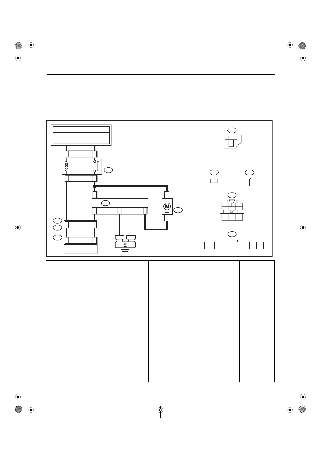
WIRING DIAGRAM:

Air conditioning system, auto A/C model <Ref. to WI-77, AUTO A/C MODEL, WIRING DIAGRAM, Air Con-

ditioning System.>

Step

Check

Yes

No

1

CHECK BLOWER MOTOR CIRCUIT.
1) Turn the ignition switch to OFF.
2) Disconnect the power transistor connector.
3) Use a tester to measure the resistance 
between the power transistor connector and 
chassis ground.

Connector & terminal

(B57) No. 3 — Chassis ground:

Is there continuity?

Repair or replace 
the short circuit of 
the harness.

Go to step 

2.

2

CHECK HARNESS.
1) Remove the auto A/C control module.
2) Use a tester to measure the resistance 
between the power transistor connector and 
chassis ground.

Connector & terminal

(B57) No. 2 — Chassis ground:

Is there continuity?

Repair or replace 
the short circuit of 
the harness.

Go to step 

3.

3

CHECK POWER TRANSISTOR.
1) Connect the disconnected connectors.
2) Turn the ignition switch to ON.
3) Use a tester to measure the voltage 
between the power transistor connector and 
chassis ground.

Connector & terminal

(B57) No. 2 (+) — Chassis ground (–):

Is the voltage approx. 10 V 
when fan dial in 1st, and 
approx. 1 V when fan dial in 
7th?

Replace the power 
transistor. <Ref. to 
AC-27, REMOVAL, 
Power Transistor 
(Auto A/C Model).>

Go to step 

4.

B386

2

1

3

4

23

11

i1

5 6 7 8

2

1

9

4

3

10

24

22

23

25

27

26

28

11 12 13

14 15 16

17 18 19 20 21

4

3

2

1

B57

2

1

B87

12

B57

4

2

3

1

B87

9

i1

B36

B386

1

2

4

3

1 2 3 4 5 6 7 8 9 10 11 12 13 14 15 16 17 18 19 20

21 22 23 24 25 26 27 28 29 30 31 32 33 34 35 36 37 38 39 40

i88

40

i88

AC-02508

AUTO A/C 

CONTROL MODULE

TO POWER SUPPLY CIRCUIT

FB-46

F/B FUSE NO. 22

(IG)

FB-8

F/B FUSE NO.27 (B)

F/B FUSE NO.28 (B)

BLOWER MOTOR RELAY

BLOWER 

MOTOR

POWER TRANSISTOR

AC(diag)-18

Diagnostics for A/C System Malfunction

HVAC SYSTEM (AUTO A/C) (DIAGNOSTICS)

4

CHECK AUTO A/C CONTROL MODULE.
1) Turn the fan dial OFF.
2) Disconnect the power transistor connector.
3) Use a tester to measure the resistance 
between the power transistor connector and 
chassis ground.

Connector & terminal

(B57) No. 2 — Chassis ground:

When the fan dial is OFF and 
other than OFF, does the resis-
tance change?

Replace the power 
transistor. <Ref. to 
AC-27, REMOVAL, 
Power Transistor 
(Auto A/C Model).>

Replace the auto 
A/C control mod-
ule. <Ref. to AC-
31, REMOVAL, 
Control Unit (Auto 
A/C Model).>

Step

Check

Yes

No

AC(diag)-19

Diagnostics for A/C System Malfunction

HVAC SYSTEM (AUTO A/C) (DIAGNOSTICS)

D: COMPARTMENT TEMPERATURE DOES NOT CHANGE, OR A/C SYSTEM 

DOES NOT RESPOND PROMPTLY

TROUBLE SYMPTOM:

• Compartment temperature does not change. (Cold air does not come out.)

• A/C system does not respond. (Response is extremely slow)

WIRING DIAGRAM:

Air conditioning system, auto A/C model <Ref. to WI-77, AUTO A/C MODEL, WIRING DIAGRAM, Air Con-

ditioning System.>

Step

Check

Yes

No

1

CHECK FUSE.
1) Turn the ignition switch to OFF.
2) Remove the fuse No. 22 from fuse & relay 
box.
3) Check the condition of fuse.

Is the fuse blown out?

Replace the fuse. Go to step 

2.

ECM

i1

5 6 7 8

2

1

9

4

3

10

24

22

23

25

27

26

28

11 12 13

14 15 16

17 18 19 20 21

C: F35

1 2

3 4 5

6 7 8 9 10 11 12

B: B143

1 2 3 4

5 6 7 8 9

10 11 12 13 14 15 16 17 18 19 20

A: F37

1 2 3 4

5 6 7 8 9

10 11 12 13 14 15 16 17 18 19 20

B360

1 2 3

4 5 6 7

8 9 10 11 12 13 14 15 16

1
7

B361

2 3

4 5 6

8 9 10 11 12 13 14

B: B135

5

6

7

2

1

3

4

29

10 11 12 13 14 15

25

24

16

30

9

8

17 18 19

20
28

21 22 23

32

31

26 27

33

34 35

B436

B434

B435

1 2 3 4 5

B10

2

3

1

4

4

4

4

B434

B436

B435

5

AC-02396

C29

B36

i1

24

F24

i88

1 2 3 4 5 6 7 8 9 10 11 12 13 14 15 16 17 18 19 20

21 22 23 24 25 26 27 28 29 30 31 32 33 34 35 36 37 38 39 40

F27

12

11

10

18
19

16

15

17

9

20 21 22

8

4 5

3

2

1

7

6

14

13

C7

B35

B135

B:

B136

C:

4

1

3

2

1

9

F109

B360

14

9

F108

B361

C: B136

16

10 11 12 13 14 15

25

24

30

9

8

7

17 18 19 20
28

21 22 23

29

32

31

1

2

3

4

5

6

27

26

33 34 35

C7

C3

B13

A4

F35

C:

B143

F37

B:

A:

36

15

17

14

16

F27

B10

11

i88

TO POWER SUPPLY

 CIRCUIT

PRESSURE  SWITCH

AUTO A/C

 CONTROL 

MODULE

A/C 

RELAY

MAIN 

FUSE BOX 

(M/B)

THR

OUGH JOINT 

CONNECT

OR

THROUGH JOINT 

CONNECTOR

RELAY HOLDER

A/C COMPRESSOR

MAGNET 

CLUTCH

FB-46

F/B FUSE NO. 22

(IG)

MULTI JOINT

 CONNECTOR

AC(diag)-20

Diagnostics for A/C System Malfunction

HVAC SYSTEM (AUTO A/C) (DIAGNOSTICS)

2

CHECK SIGNAL TO A/C RELAY AND AUTO 
A/C CONTROL MODULE.
1) Disconnect the A/C relay and auto A/C con-
trol module harness connector.
2) Turn the ignition switch to ON.
3) Measure the voltage between A/C relay 
connector terminal and chassis ground.
4) Measure the voltage between auto A/C con-
trol module harness connector terminal and 
chassis ground.

Connector & terminal

(F27) No. 17 (+) — Chassis ground (–):
(i88) No. 11 (+) — Chassis ground (–):

Is the voltage 10 V or more?

Go to step 

5.

Go to step 

3.

3

CHECK POWER SUPPLY FOR PRESSURE 
SWITCH.
1) Turn the ignition switch to OFF.
2) Disconnect the pressure switch harness 
connector.
3) Turn the ignition switch to ON.
4) Measure the voltage between pressure 
switch harness connector terminal and chassis 
ground.

Connector & terminal

(B10) No. 2 (+) — Chassis ground (–):

Is the voltage 10 V or more?

Go to step 

4.

Check for open or 
short circuit in the 
harness between 
fuse and pressure 
switch.

4

CHECK HARNESS BETWEEN PRESSURE 
SWITCH AND A/C RELAY, AUTO A/C CON-
TROL MODULE.
1) Turn the ignition switch to OFF.
2) Measure the resistance of harness between 
pressure switch connector and A/C relay con-
nector.
3) Measure the resistance of harness between 
pressure switch connector and auto A/C control 
module connector.

Connector & terminal

(B10) No. 2 — (F27) No. 17:
(B10) No. 2 — (i88) No. 11:

Is the resistance less than 1 Ω? Check the pres-

sure switch. <Ref. 
to AC-43, INSPEC-
TION, Pressure 
Switch (Triple 
Pressure Switch).>

Repair the har-
ness.

5

CHECK POWER SUPPLY FOR A/C RELAY.
Measure the voltage between A/C relay con-
nector terminal and chassis ground.

Connector & terminal

(F27) No. 14 (+) — Chassis ground (–):

Is the voltage 10 V or more?

Go to step 

6.

Check open or 
short circuit of har-
ness between fuse 
and A/C relay.

6

CHECK A/C RELAY.
Check the A/C relay. <Ref. to AC-42, INSPEC-
TION, Relay and Fuse.>

Is the A/C relay normal?

Go to step 

7.

Replace the A/C 
relay.

7

CHECK A/C ON SIGNAL.
1) Turn the ignition switch to OFF.
2) Connect the A/C relay and all disconnected 
connectors.
3) Start the engine and turn the A/C switch to 
ON.
4) Turn the temperature control dial at maxi-
mum cool position.
5) Measure the voltage between auto A/C con-
trol module harness connector terminal and 
chassis ground.

Connector & terminal

(i88) No. 36 (+) — Chassis ground (–):

Is the voltage 5.5 V or more?

Go to step 

8.

Replace the auto 
A/C control mod-
ule. <Ref. to AC-
31, REMOVAL, 
Control Unit (Auto 
A/C Model).>

Step

Check

Yes

No


Content   ..  601  602  603  604   ..