Subaru Impreza 3 / Impreza WRX / Impreza WRX STI. Manual - part 601
AC(diag)-9
Diagnostic Chart for Self-Diagnosis
HVAC SYSTEM (AUTO A/C) (DIAGNOSTICS)
5. Diagnostic Chart for Self-Diagnosis
A: OPERATION
1. A/C CONTROL MODULE SELF-DIAGNOSIS
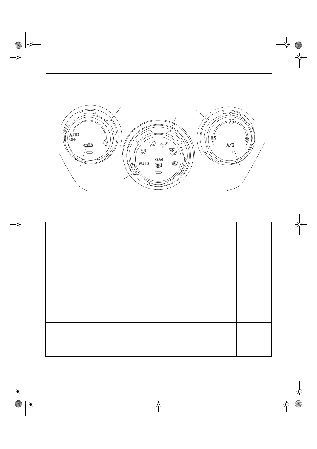
(1)
Fan dial
(3)
Temperature adjustment dial
(5)
Rear window defogger switch
(2)
Air flow control dial
(4)
FRESH/RECIRC switch
(6)
A/C switch
Step
Check
Yes
No
1
SELECT SELF-DIAGNOSIS MODE IN THE
CONTROL MODULE.
1) Set the air flow control dial and fan dial to the
AUTO position.
2) Start the engine with the A/C switch and the
FRESH/RECIRC switch pressed.
Does the self-diagnosis mode
operate?
2
CHECK THE LIGHTING OF THE LED.
Make sure that all switch LEDs on the control
module illuminate.
Do all LEDs blink eight times? Go to step
Replace the con-
trol module.
3
CHECK SENSOR MALFUNCTION.
1) Set the air flow control dial and fan dial to the
AUTO position.
2) If the system has trouble for each sensor,
the FRESH/RECIRC switch LED blinks or is
turned off.
3) If the system has no malfunctions, the
FRESH/RECIRC switch LED is illuminated.
Does the FRESH/RECIRC
switch LED illuminate?
4
CONFIRM MALFUNCTIONING SENSOR.
1) Set the air flow control dial to AUTO.
2) Turn the fan dial to each mode position, and
check each switch LED illumination according
to sensor check table. <Ref. to AC(diag)-11,
SENSOR CHECK TABLE, OPERATION, Diag-
nostic Chart for Self-Diagnosis.>
When turning the fan dial to
each mode position, does the
FRESH/RECIRC switch LED
go off?
Repair the defec-
tive sensor. <Ref.
to AC(diag)-29,
Diagnostic Proce-
dure for Sensors.>
(5)
(2)
(6)
(1)
(4)
(3)
AC-02014