Subaru Impreza 3 / Impreza WRX / Impreza WRX STI. Manual - part 600
AC(diag)-5
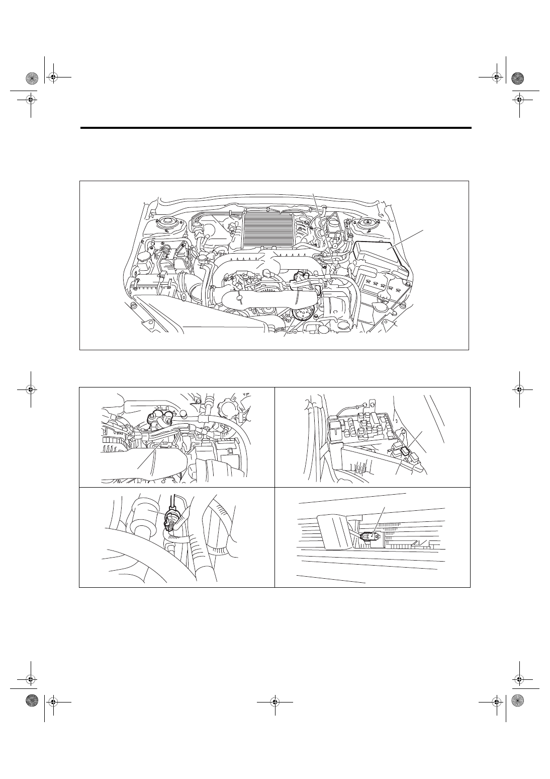
Electrical Component Location
HVAC SYSTEM (AUTO A/C) (DIAGNOSTICS)
3. Electrical Component Location
A: LOCATION
1. ENGINE COMPARTMENT
(1)
A/C compressor
(3)
Pressure switch
(4)
Ambient sensor
(2)
A/C relay
AC-01879
(2)
(1)
(3)
AC-02013
(1)
(2)
AC-01603
AC-00814
(3)
AC-00816
(4)