Subaru Impreza 3 / Impreza WRX / Impreza WRX STI. Manual - part 569


  Index      Subaru     Subaru Impreza 3 / Impreza WRX / Impreza WRX STI - service repair manual 2008-2014 year


Search            


Content   ..  567  568  569  570   ..


Subaru Impreza 3 / Impreza WRX / Impreza WRX STI. Manual - part 569


PB-7

Parking Brake Assembly (Rear Disc Brake)

PARKING BRAKE

8) Remove  the  brake  shoe  cup  and  brake  shoe

spring, and remove the primary brake shoe.

9) Remove the strut and strut spring.

10) Remove the adjuster.

11) Remove  brake  shoe  cup  and  brake  shoe

spring, and remove the secondary brake shoe.

12) Remove the parking brake cable from lever.

13) Remove  a  retainer  from  the  secondary  side

brake shoe. Remove the lever from the brake shoe.

B: INSTALLATION

CAUTION:

Be sure the lining surface is free from brake flu-

id and grease.

1) Apply brake grease to the following locations.
Brake grease:

Brake Grease (Part No. 003602002)

• Six contact surfaces of the brake shoe rim and

back plate gasket

• Contact  surface  of  the  brake  shoe  and  the  an-

chor pin

• Contact surface of the parking brake lever and

strut

• Contact surface of the brake shoe and adjuster

• Contact surface of the brake shoe and strut

• Contact surface of the lever and brake shoe

2) Install the wave washer and lever to the second-

ary side brake shoe pin, and lock the retainer se-

curely.

3) Install the parking brake cable to the lever.

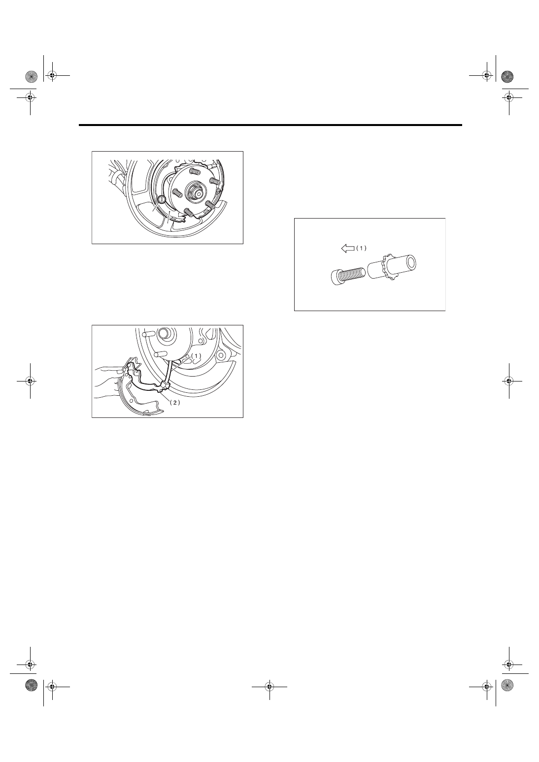
4) Install  the  adjuster  and  adjusting  spring  to  the

brake shoe.
NOTE:

Install the adjuster with screw section on the direc-

tion side in the figure below.

5) Check that the parking brake cable does not fall

from the cable guide.

6) Install  the  brake  shoes  to  the  back  plate  with

shoe  hold  pins,  brake  shoe  springs,  and  brake

shoe cups.

7) Install  the  strut  and  strut  spring  to  the  brake

shoes.
NOTE:

Install the strut springs on front side of the vehicle.

8) Install the return springs on the primary side first,

and then the secondary side.

9) Install the rear disc rotors and rear caliper body

assembly.
Tightening torque:

Caliper body assembly (brembo type)

65 N·m (6.63 kgf-m, 47.9 ft-lb)

Caliper body assembly (except for brembo 

type)

66 N·m (6.73 kgf-m, 48.7 ft-lb)

10) Install the brake hose bracket.
Tightening torque:

33 N·m (3.36 kgf-m, 24.3 ft-lb)

11) Adjust  the  parking  brake.  <Ref.  to  PB-8,  AD-

JUSTMENT, Parking Brake Assembly (Rear Disc

Brake).>

12) If new brake shoes are replaced, drive the ve-

hicle to break-in the parking brake lining.

(1) Drive the vehicle at approximately 35 km/h

(22 MPH) or more.

(1) Brake shoe cup
(2) Primary brake shoe

(1) Parking brake cable
(2) Lever

(1)

(2)

PB-00096

PB-00014

(1) Left wheel: front side of vehicle, right wheel: 

rear side of vehicle

PB-00840

PB-8

Parking Brake Assembly (Rear Disc Brake)

PARKING BRAKE

(2) While pressing the parking brake lever but-

ton, pull the parking brake lever with a force of

150 N (15.3 kgf, 33.7 lbf).

(3) Drive the vehicle for about 200 m (0.12 mile)

in this condition.

(4) Wait 5 to 10 minutes for the parking brake to

cool down. Repeat steps (1) through (3) again.

(5) After  breaking-in,  re-adjust  the  parking

brakes.

C: INSPECTION

1) Measure the inner diameter of the disc rotor. If

scoring  or  worn  is  found  on  the  disc,  replace  the

disc rotor.
Disc rotor inner diameter:

Standard

190 mm (7.48 in)

Service limit

191 mm (7.52 in)

2) Measure  the  lining  thickness.  If  it  exceeds  the

limit, replace the brake shoe.
Lining thickness:

Standard

2.8 mm (0.11 in)

Service limit

1.5 mm (0.059 in)

NOTE:

Replace the right and left brake shoe as a set.

D: ADJUSTMENT

1. SHOE CLEARANCE

1) Return the parking brake lever fully.

2) Loosen  the  adjusting  nut,  and  make  the  cable

free.

3) Remove the adjusting hole cover from the disc

rotor.

4) Using a flat tip screwdriver, turn the adjuster in

the direction of the arrow as shown in the figure to

an extent that the disc rotor cannot be rotated by

both hands.

5) Loosen the adjuster by 5 notches in the opposite

direction of the arrow.
CAUTION:

• Check there is no brake drag.

• If  the  return  amount  of  adjuster  is  insuffi-

cient, be sure to loosen it by 5 notches to avoid

dragging.

6) Install the adjusting hole cover to the disc rotor.

7) Adjust  the  parking  lever  stroke.  <Ref. to  PB-8,

LEVER  STROKE,  ADJUSTMENT,  Parking  Brake

Assembly (Rear Disc Brake).>

2. LEVER STROKE

1) Adjust the shoe clearance before adjusting lever

stroke.  <Ref.  to  PB-8,  SHOE  CLEARANCE,  AD-

JUSTMENT, Parking Brake Assembly (Rear Disc

Brake).>

2) Remove the parking lever cover.

3) Pull the parking brake lever hard 3 to 5 times.

4) Turn the adjusting nut until the lever stroke is at

the specified value.
Lever stroke:

7 to 8 notches when pulled with a force of 200 

N (20.4 kgf, 45 lbf)

5) Check there is no brake drag.

6) Install the parking lever cover.

(1) Adjuster
(2) Flat tip screwdriver
(3) Disc rotor

(1)

(3)

(2)

PM-00537

(1) Adjusting nut (self-locking nut)

PB-00054

(1)

PB-9

General Diagnostic Table

PARKING BRAKE

5. General Diagnostic Table

A: INSPECTION

Symptoms

Possible cause

Corrective action

Brake drag

Parking brake lever not adjusted correctly.

Adjust.

Parking brake cable does not move.

Repair or replace.

Parking brake shoe clearance is maladjusted.

Adjust.

Return spring is faulty.

Replace.

Noise from brake

Return spring is faulty.

Replace.

Shoe hold-down spring faulty.

Replace.

PB-10

General Diagnostic Table

PARKING BRAKE


Content   ..  567  568  569  570   ..