Subaru Impreza 3 / Impreza WRX / Impreza WRX STI. Manual - part 563
BR-37
Brake Booster
BRAKE
1. OPERATION CHECK (WITHOUT GAUG-
ES)
CAUTION:
When checking operation, be sure to apply the
parking brake securely.
• Check without gauges
This method can not determine exactly what part is
defective. But it is possible to identify the outline of
the defect by performing the check according to the
following procedures.
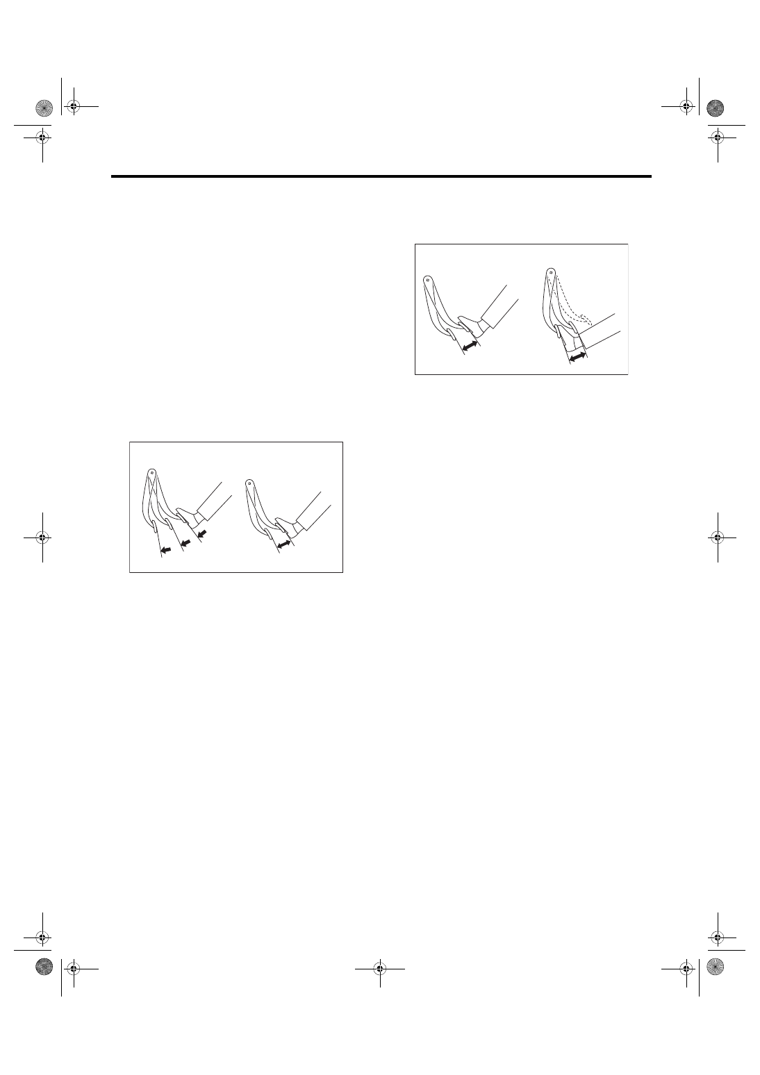
• Air tightness check
Start the engine, and idle it for 1 to 2 minutes, then
turn it OFF. Depress the brake pedal several times
applying the normal pedal force. The pedal stroke
should be the longest at the 1st depression, and it
should become shorter at each successive depres-
sion. If no change occurs in the pedal height when
pressed, the brake booster is faulty.
NOTE:
• In case of defective operation, inspect the condi-
tion of the check valve and vacuum hose as well.
• Replace them if faulty, and perform the test
again.
• If no improvement is observed, check precisely
with gauges.
• Check operation
1) While the engine is OFF, depress the brake ped-
al several times applying the same pedal force, to
check for a change in pedal height.
2) With the brake pedal depressed, start the en-
gine.
3) As the engine starts, the brake pedal should
move slowly toward the floor. If the pedal height
does not change, the brake booster is faulty.
NOTE:
If faulty, check precisely with gauges.
• Loaded air tightness check
Depress the brake pedal while the engine is run-
ning, and turn the engine to OFF while the pedal is
depressed. Keep the pedal depressed for 30 sec-
onds. If the pedal height does not change, the func-
tion of brake booster is normal. If the pedal height
increases, it is faulty.
NOTE:
If faulty, check precisely with gauges.
(1) Normal
(2) Not OK
(3) 1st
(4) 2nd
(5) 3rd
BR-00080
(1)
(3)
(4)
(5)
(2)
(1) When engine is stopped
(2) When engine is started
BR-00081
(1)
(2)