Subaru Impreza 3 / Impreza WRX / Impreza WRX STI. Manual - part 564


  Index      Subaru     Subaru Impreza 3 / Impreza WRX / Impreza WRX STI - service repair manual 2008-2014 year


Search            


Content   ..  562  563  564  565   ..


Subaru Impreza 3 / Impreza WRX / Impreza WRX STI. Manual - part 564


BR-41

Air Bleeding

BRAKE

11.Air Bleeding

A: PROCEDURE

CAUTION:

• Do not let brake fluid come into contact with

the painted surface of the vehicle body. Wash

away with water immediately and wipe off if it is

spilled by accident.

• Avoid mixing brake fluid of different brands

to prevent fluid performance from degrading.

• Be careful not to allow dirt or dust to enter the

reservoir tank.

1. MASTER CYLINDER

NOTE:

• When the master cylinder is disassembled or the

reservoir tank is empty, bleed the master cylinder.

• If bleeding of the master cylinder is not neces-

sary,  omit  the  following  procedures,  and  perform

bleeding of the brake line. <Ref. to BR-41, BRAKE

LINE, PROCEDURE, Air Bleeding.>

1) Fill the reservoir tank of the master cylinder with

brake fluid.
NOTE:

While  bleeding  air,  keep  the  reservoir  tank  filled

with brake fluid to prevent entry of air.

2) Disconnect  the  brake  line  at  primary  and  sec-

ondary sides.

3) Wrap the master cylinder with a plastic bag.

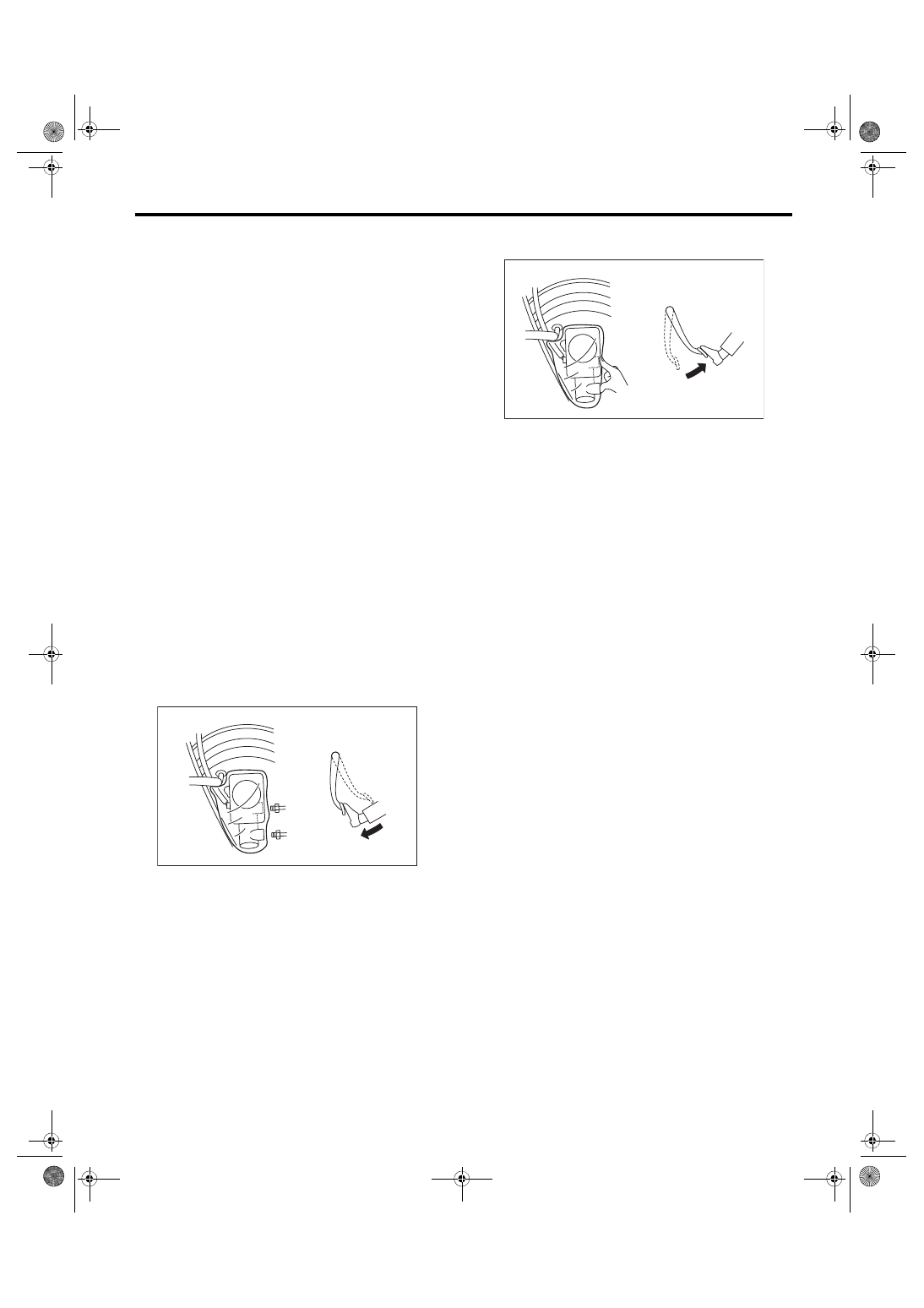
4) Depress the brake pedal slowly and hold it.

NOTE:

On the model with brake assist mechanism, the fol-

lowing phenomena occur when the brake pedal is

depressed. However, those are not malfunction but

the phenomena that occur when the brake assist

mechanism functions properly.

• Brake feel is soft when brake pedal is depressed

hard or quicker than usual.

• ABS operating sound is heard when brake pedal

is depressed hard or quicker than usual.

5) Plug the outlet plug with your finger, and then re-

lease the brake pedal.

6) Repeat the step 4) and 5) several times.

7) Remove the plastic bag.

8) Install the brake pipe to the master cylinder.
Tightening torque:

19 N·m (1.94 kgf-m, 14 ft-lb)

9) Bleed  air  from  the  brake  line.  <Ref.  to  BR-41,

BRAKE LINE, PROCEDURE, Air Bleeding.>

2. BRAKE LINE

1) When the master cylinder is disassembled or the

reservoir tank is empty, bleed the master cylinder

before  bleeding  the  brake  line.  <Ref.  to  BR-41,

MASTER  CYLINDER,  PROCEDURE,  Air  Bleed-

ing.>

2) Fill the reservoir tank of the master cylinder with

brake fluid.
NOTE:

While  bleeding  air,  keep  the  reservoir  tank  filled

with brake fluid to prevent entry of air.

3) Attach one end of the vinyl tube to the air bleeder

and the other end to the brake fluid container.

4) Depress the brake pedal several times, and hold

it.

BR-00090

BR-00091

BR-42

Air Bleeding

BRAKE

5) Loosen the air bleeder screw to drain brake fluid.

Tighten  the  air  bleeder  quickly,  and  release  the

brake pedal.
NOTE:

• Bleed air in order starting from the wheel cylinder

farthest from the master cylinder.

• For calipers with two air bleeder screws, bleed

air from the inner side first and then the outer side.

Repeat this operation at least twice.

6) Repeat the steps 4) to 5) until there are no more

air bubbles in the vinyl tube.

7) Repeat the steps from 2) to 6) above to bleed air

from each wheel.

8) Securely tighten the air bleeder screws.
Tightening torque:

Brembo type

20 N·m (2.04 kgf-m, 14.5 ft-lb)

Except for 1 brembo type

8 N·m (0.82 kgf-m, 5.9 ft-lb)

9) Check that there are no brake fluid leaks in the

entire system.

10) Check the pedal stroke.

Run the engine at idle after warming up the engine,

and depress the brake pedal with a force of 500 N

(51 kgf, 112 lbf). Measure the distance between the

brake pedal and steering wheel. Release the pedal,

and  measure  the  distance  between  pedal  and

steering wheel again.

Specification of pedal stroke:

When depressing the pedal with a force of 

500 N (51 kgf, 112 lbf).

110 mm (4.33 in) or less

11) If the distance is more than specification, there

is a possibility of air being caught in the brake line.

Bleed the brake line of all air until the pedal stroke

meets the specification.

12) Operate  the  hydraulic  control  unit  in  the  se-

quence control mode. <Ref. to VDC-14, ABS Se-

quence Control.>

13) Check the pedal stroke again.

14) If the distance is more than specification, there

is a possibility of air being caught in the hydraulic

unit.  Repeat  above  steps  2)  to  9)  until  the  pedal

stroke meets the specification.

15) Fill the reservoir tank with brake fluid up to the

“MAX” level.

16) Test run the vehicle and ensure that the brakes

operate normally.

(1) Inner side air bleeder screw
(2) Outer side air bleeder screw

BR-00376

(2)

(1)

(1) Steering wheel
(2) Toe board

BR-00094

(1)

(2)

1

2

2

1

BR-43

Brake Hose

BRAKE

12.Brake Hose

A: REMOVAL

1. FRONT BRAKE HOSE

1) Separate the brake pipe from brake hose using a

flare nut wrench.

2) Remove  the  clamp,  the  strut  mount  bolts,  and

union bolt.

2. REAR BRAKE HOSE

1) Remove union bolt and brake hose bracket bolt.

• Brembo type

• Except for brembo type

2) Separate the brake pipe from brake hose using a

flare nut wrench.

3) Remove the clamp, and then remove the brake

hose.

(1) Brake hose
(2) Brake pipe

BR-00095

(1)

(2)

BR-00702

(1) Brake pipe
(2) Brake hose clamp
(3) Brake hose

BR-00744

(1)

(2)

(3)

BR-00670

BR-44

Brake Hose

BRAKE

B: INSTALLATION

1. FRONT BRAKE HOSE

1) Secure the brake hose to strut mount.
Tightening torque:

33 N·m (3.36 kgf-m, 24.3 ft-lb)

2) Install the brake hose to the caliper using a new

gasket.
Tightening torque (union bolt):

18 N·m (1.84 kgf-m, 13.3 ft-lb)

3) Position  the  disc  in  straight  position  and  route

the brake hose through the hole in the bracket on

the wheel apron side.
CAUTION:

Do not twist the brake hose.

4) Temporarily tighten the flare nut which connects

brake pipe and hose.

5) Secure the brake hose to wheel apron bracket

with clamp.

6) Tighten the flare nut to the specified torque.
Tightening torque (brake pipe flare nut):

15 N·m (1.53 kgf-m, 11.1 ft-lb)

7) Bleed air from the brake system. <Ref. to BR-41,

PROCEDURE, Air Bleeding.>

2. REAR BRAKE HOSE

1) Route the brake hose through the hole of brack-

et, and lightly tighten the flare nut to connect brake

pipe.

2) Insert the clamp to secure brake hose.

3) Install the brake hose bracket.
Tightening torque:

33 N·m (3.36 kgf-m, 24.3 ft-lb)

4) Install the brake hose to rear brake caliper using

a new gasket.
Tightening torque (union bolt):

18 N·m (1.84 kgf-m, 13.3 ft-lb)

• Brembo type

• Brembo type

5) Tighten the flare nut to the specified torque.
Tightening torque (brake pipe flare nut):

15 N·m (1.53 kgf-m, 11.1 ft-lb)

6) Bleed air from the brake system. <Ref. to BR-41,

PROCEDURE, Air Bleeding.>

(1) Brake pipe
(2) Brake hose clamp
(3) Brake hose

(1)

(2)

(3)

BR-00670

BR-00702

BR-00744


Content   ..  562  563  564  565   ..