Subaru Impreza 3 / Impreza WRX / Impreza WRX STI. Manual - part 561


  Index      Subaru     Subaru Impreza 3 / Impreza WRX / Impreza WRX STI - service repair manual 2008-2014 year


Search            


Content   ..  559  560  561  562   ..


Subaru Impreza 3 / Impreza WRX / Impreza WRX STI. Manual - part 561


BR-29

Rear Disc Brake Assembly

BRAKE

7. Rear Disc Brake Assembly
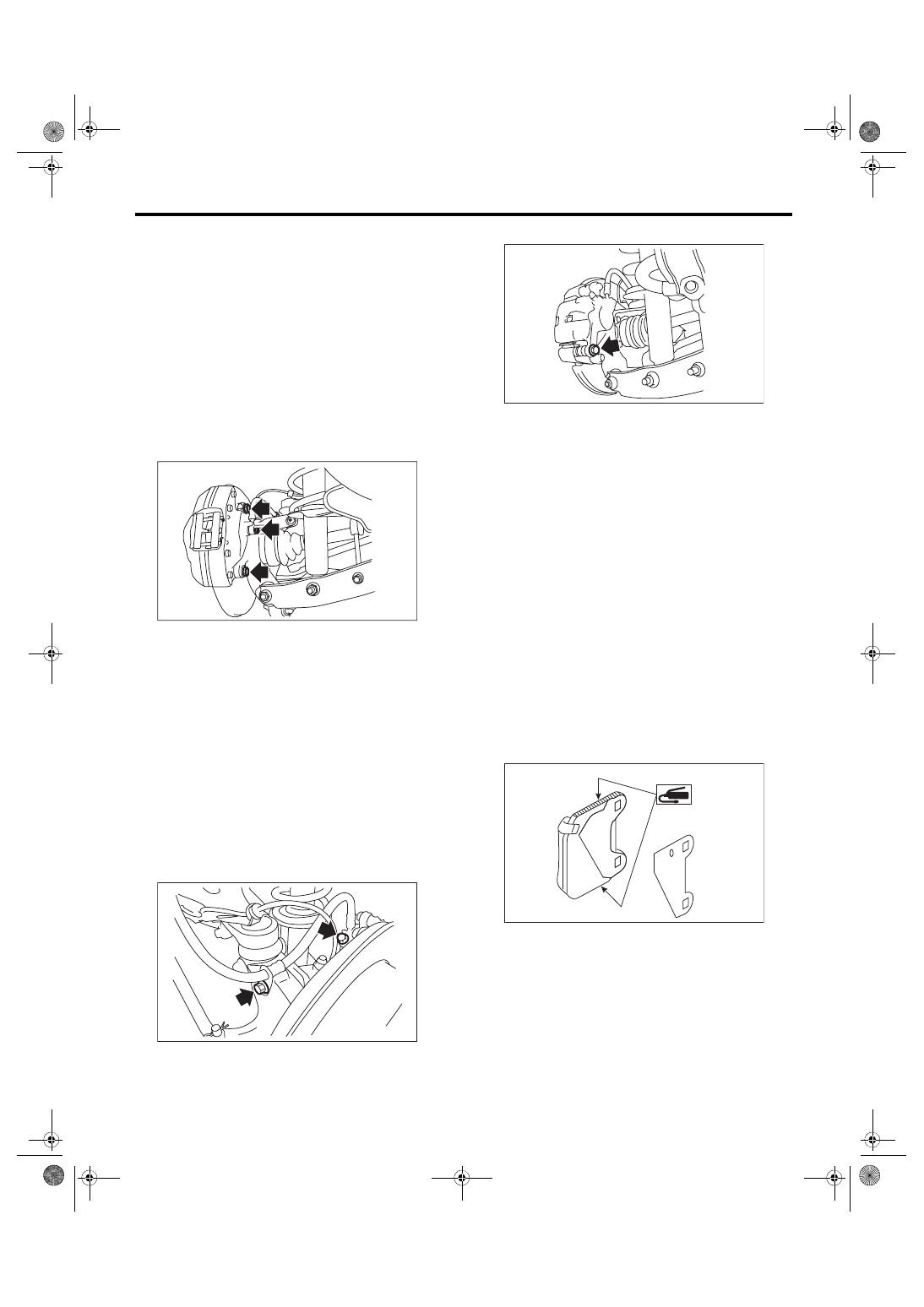
A: REMOVAL

1. BREMBO TYPE

CAUTION:

Do not allow brake fluid to come in contact with

the  painted  surface  of  the  vehicle  body.  If  it

does, wash off with water and wipe away com-

pletely.

1) Lift  up  the  vehicle,  and  then  remove  the  rear

wheels.

2) Remove the union bolt and brake hose from the

caliper body.

3) Remove the caliper body assembly.

4) Remove mud and foreign matter from the caliper

body assembly.
CAUTION:

Be careful not to allow foreign matter to enter

the brake hose connector.

2. EXCEPT FOR brembo TYPE

CAUTION:

Do not allow brake fluid to come in contact with

the  painted  surface  of  the  vehicle  body.  If  it

does, wash off with water and wipe away com-

pletely.

1) Lift  up  the  vehicle,  and  then  remove  the  rear

wheels.

2) Remove the brake hose bracket.

3) Disconnect the brake hose.

4) Remove the caliper mounting bolts.

5) Raise the caliper body, and then move it toward

vehicle center to separate it from the support.

6) Remove  the  brake  pad,  and  then  remove  the

support from the housing.
NOTE:

Remove the support only when replacing the rotor

or support. It is not necessary to remove it when

servicing the caliper body.

7) Remove mud and foreign matter from the caliper

body and the support.
CAUTION:

Be careful not to allow foreign matter to enter

the brake hose connector.

B: INSTALLATION

1. BREMBO TYPE

1) Install the caliper body to the housing.
Tightening torque:

65 N·m (6.63 kgf-m, 47.9 ft-lb)

2) Apply a thin coat of Molykote M7439 or grease

contained in the pad kit to the pad side.

BR-00704

BR-00662

BR-00660

BR-00784

BR-30

Rear Disc Brake Assembly

BRAKE

3) Apply a thin coat of Molykote AS880N (Part No.

K0777YA010) or the grease contained in the pad

kit to the contact surface between the pad and pad

shim.

4) Install the pads to the caliper body.

5) Install the cross spring and pad pins.

6) Install the clips.

7) Connect the brake hose using a new brake hose

gasket.
Tightening torque:

18 N·m (1.84 kgf-m, 13.3 ft-lb)

8) Bleed air from the brake system. <Ref. to BR-41,

PROCEDURE, Air Bleeding.>

2. EXCEPT FOR BREMBO TYPE

1) Apply a thin coat of Molykote M7439 or grease

contained in the pad kit to the support.

2) Install the support to the housing.
Tightening torque:

66 N·m (6.73 kgf-m, 48.7 ft-lb)

3) Apply a thin coat of Molykote M7439 or grease

contained in the pad kit to the pad clip.

4) Apply a thin coat of Molykote AS880N (Part No.

K0777YA010)  or  grease  contained  in  the  pad  kit

between the outer pad and shim.

5) Apply a thin coat of Molykote AS880N (Part No.

K0777YA010) or grease contained in the pad kit to

both surfaces of the inner pad inner shim.

6) Install the pad to support.

7) Install the caliper body to the support.
Tightening torque:

27 N·m (2.75 kgf-m, 19.9 ft-lb)

8) Install the brake hose bracket.
Tightening torque:

33 N·m (3.36 kgf-m, 24.3 ft-lb)

9) Connect the brake hose using a new brake hose

gasket.
Tightening torque:

18 N·m (1.84 kgf-m, 13.3 ft-lb)

10) Bleed air from the brake system. <Ref. to BR-

41, PROCEDURE, Air Bleeding.>

BR-00785

BR-00597

BR-00599

BR-00875

BR-00876

BR-31

Rear Disc Brake Assembly

BRAKE

C: DISASSEMBLY

1. BREMBO TYPE

1) Remove the piston boots from each piston end.

2) Place  a  wooden  block  in  the  caliper  body  as

shown in the figure to prevent the piston from jump-

ing out and being damaged.

3) Gradually  apply  compressed  air  via  the  brake

hose installation hole to push the piston out.

4) Remove the piston seal from caliper body cylin-

der.
CAUTION:

Do  not  damage  the  cylinder  and  piston  seal

groove.

2. EXCEPT FOR BREMBO TYPE

1) Remove the piston boot.

2) Place  a  wooden  block  in  the  caliper  body  as

shown in the figure to prevent the piston from jump-

ing out and being damaged.

3) Gradually  apply  compressed  air  via  the  brake

hose installation hole to push the piston out.

4) Remove the piston seal from caliper body cylin-

der.
CAUTION:

Do  not  damage  the  cylinder  and  piston  seal

groove.

5) Remove the pin boot.

(1) Place a wooden block of 20 mm (0.79 in) width.

BR-00317

(1)

BR-00318

BR-00319

(1) Place a wooden block of 30 mm (1.18 in) width.

BR-00041

BR-00042

(1)

BR-00043

BR-32

Rear Disc Brake Assembly

BRAKE

D: ASSEMBLY

1. BREMBO TYPE

1) Clean the inside of the caliper body using brake

fluid.

2) Apply a coat of brake fluid to the piston seal and

install in the caliper body groove.

3) Apply a coat of brake fluid to the inner surface

and the entire outer surface of the cylinder.

4) Apply NIGLUBE RX-2 (Part No. K0779GA102)

or the pad kit grease to the boot, and install to the

piston groove.

5) Insert the piston into the cylinder.
CAUTION:

Do not force the piston into cylinder.

6) Position the boot in the grooves on piston and

cylinder.

2. EXCEPT FOR BREMBO TYPE

1) Clean the inside of the caliper body using brake

fluid.

2) Apply a coat of brake fluid to piston seal and in-

stall the piston seal to the caliper body groove.

3) Apply a coat of brake fluid to the inner surface of

cylinder and the entire outer surface of the piston.

4) Apply grease contained in the piston seal kit to

the boot, and install it to the groove at the end of the

cylinder.

5) Insert the piston into cylinder.
CAUTION:

Do not force the piston into cylinder.

6) Position the boot in the grooves on piston and

cylinder.

7) Apply grease contained in the piston seal kit to

the cylinder inner surface, pin, bushing outer sur-

face, and boot grooves.

8) Insert the pin boot into the support.

9) Install the pin boot to the support, and then insert

the pin into the specified position.
CAUTION:

Insert the pin into specified position, and make

sure that they slide and seat properly.

E: INSPECTION

1) Repair or replace the faulty parts.

2) Check  the  caliper  body  and  piston  for  uneven

wear, damage or rust.

3) Check the rubber parts for damage or deteriora-

tion.

(1) Piston seal
(2) Piston boot
(3) Piston

(1)

(2)

(3)

BR-00309

(1) Piston
(2) Piston boot
(3) Caliper body
(4) Piston seal

(1) Pin boot
(2) Lock pin or guide pin
(3) Grease applied area

BR-00243

(1)

(2)

(3)

(4)

BR-00362

(1)

(2)

: (3)


Content   ..  559  560  561  562   ..