Subaru Impreza 3 / Impreza WRX / Impreza WRX STI. Manual - part 552
VDC(diag)-107
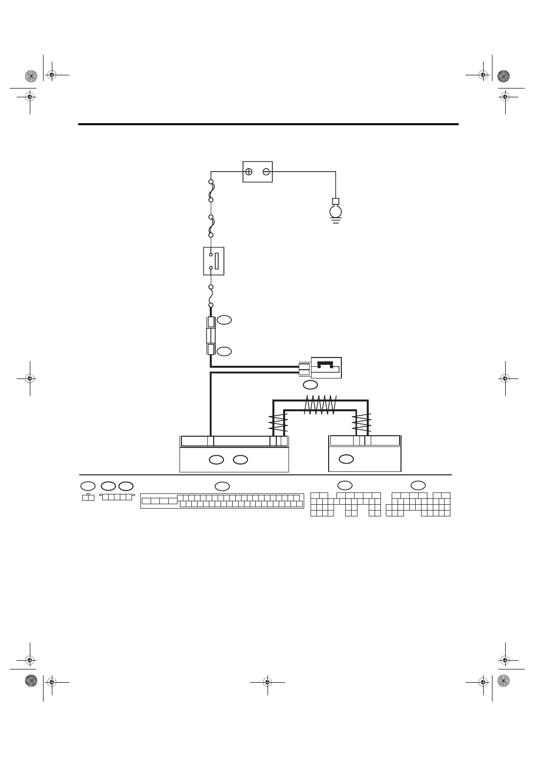
Diagnostic Procedure with Diagnostic Trouble Code (DTC)
VEHICLE DYNAMICS CONTROL (VDC) (DIAGNOSTICS)
WIRING DIAGRAM:
Engine electrical system <Ref. to WI-32, Engine Electrical System.>
VDC00891
B136
C:
B135
B:
B9
C17
C2
8
B107
B440
B441
1
2
B310
35
10
B441
B440
1
1
B: B135
29
4
3
1
2
7
6
5
10 11 12 13 14 15
25
24
16
30
9
8
17 18 19
20
28
21 22 23
32
31
26 27
33
34 35
35
27
16
10 11 12 13 14 15
25
24
30
9
8
7
17 18 19 20
28
21 22 23
29
32
31
1
2
3
4
5
6
26
33 34
B136
C:
2
1
B107
25
22
24
23
21
20
46
45
44
43
42
41
13
12
40
39
38
37
19
18
17
16
15
14
11
10
36
35
34
33
32
31
1
3
2
30
29
28
27
26
9
8
7
6
5
4
B310
5
4
3
2
1
ECM
E
SBF-
8
VDCCM & H/U
IG 2 RELAY
CLUTCH SWITCH
BATTERY
No.
4
MAIN SBF