Subaru Impreza 3 / Impreza WRX / Impreza WRX STI. Manual - part 547
VDC(diag)-87
Diagnostic Procedure with Diagnostic Trouble Code (DTC)
VEHICLE DYNAMICS CONTROL (VDC) (DIAGNOSTICS)
AM:DTC C0071 CHANGE RANGE OF STEERING ANGLE SENSOR IS TOO BIG
DTC DETECTING CONDITION:
Defective steering angle sensor
TROUBLE SYMPTOM:
VDC does not operate.
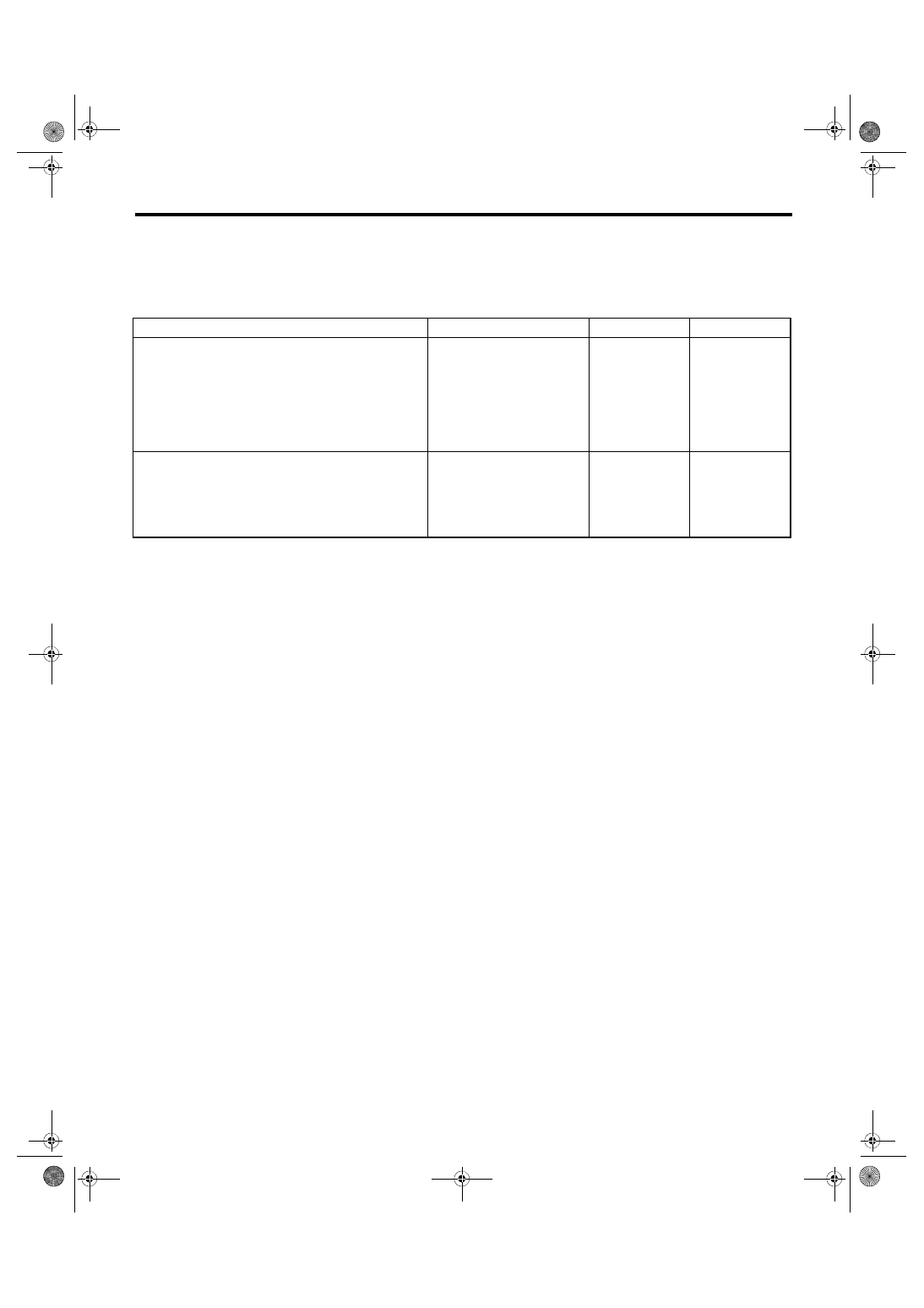
Step
Check
Yes
No
1
CHECK VDCCM&H/U.
1) Turn the ignition switch to OFF.
2) Connect all connectors.
3) Clear the memory. <Ref. to VDC(diag)-27,
Clear Memory Mode.>
4) Perform the Inspection Mode. <Ref. to
VDC(diag)-26, Inspection Mode.>
5) Read the DTC.
Is the same DTC displayed?
2
CHECK OTHER DTC DETECTION.
Is any other DTC displayed?
Temporary poor
contact occurs.