Subaru Impreza 3 / Impreza WRX / Impreza WRX STI. Manual - part 545
 

  Index      Subaru     Subaru Impreza 3 / Impreza WRX / Impreza WRX STI - service repair manual 2008-2014 year


Search            


Content   ..  543  544  545  546   ..


Subaru Impreza 3 / Impreza WRX / Impreza WRX STI. Manual - part 545


VDC(diag)-79

Diagnostic Procedure with Diagnostic Trouble Code (DTC)

VEHICLE DYNAMICS CONTROL (VDC) (DIAGNOSTICS)

AG:DTC C0054 BLS ON MALFUNCTION

DTC DETECTING CONDITION:

Defective stop light switch

TROUBLE SYMPTOM:

• ABS does not operate.

• VDC does not operate.

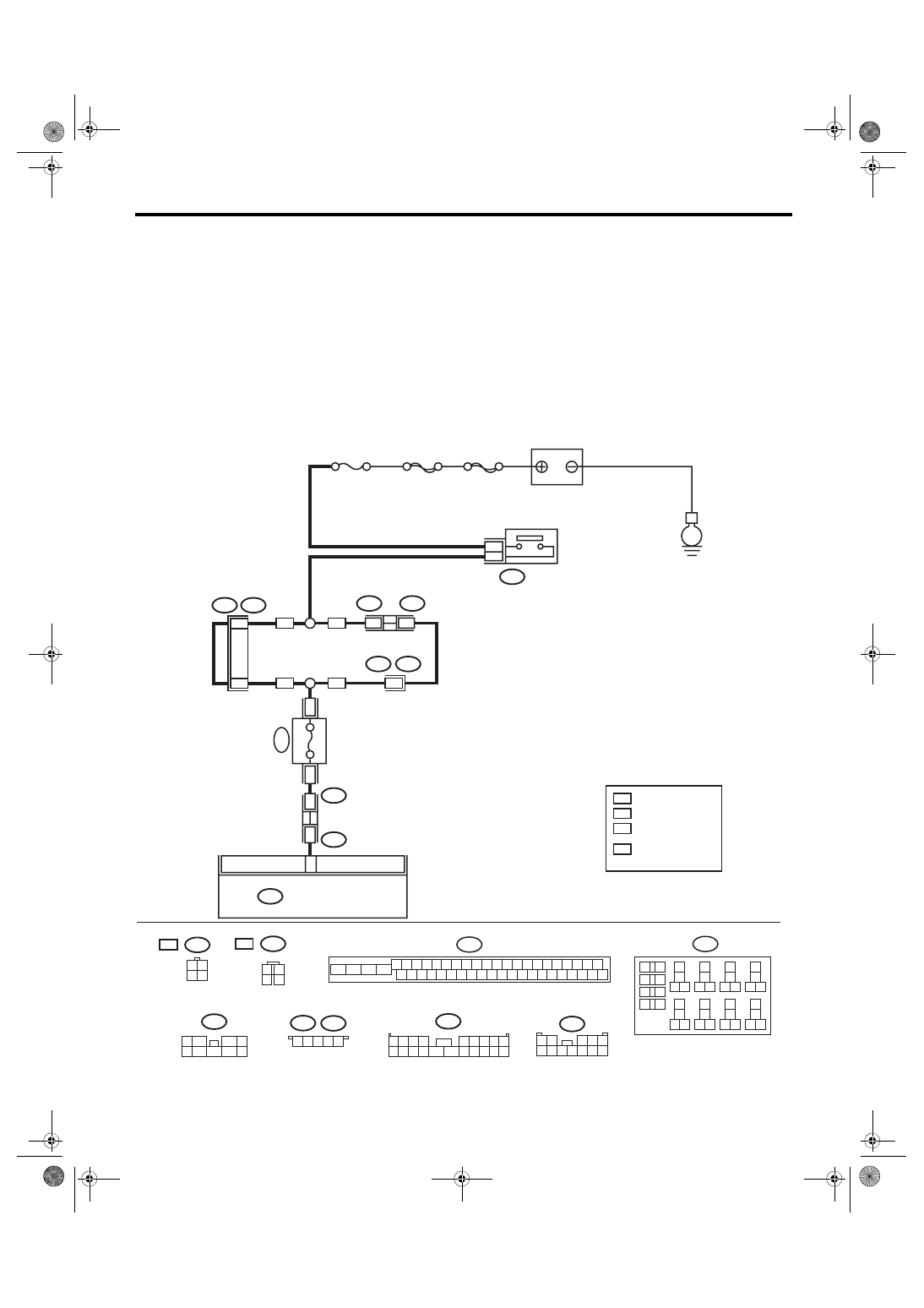
WIRING DIAGRAM:

Vehicle Dynamics Control System <Ref. to WI-67, Vehicle Dynamics Control System.>

B225

B310

4 5 6 7 8 9

26 27 28 29 30

2 3

1

31 32 33 34 35 36

10 11

14 15 16 17 18 19

37 38 39 40

12 13

41 42 43 44 45 46

20 21

23 24

22

25

22

9

15

1 2
3 4

B225

21

5Dr

4Dr

7

4Dr

4Dr

6

7

9

4

7

6

2

1
5

3
8

B65

1 2
3 4

1 2 3 4 5

B65

1 2 3 4

5 6 7 8 9

10 11 12 13 14 15 16 17 18 19 20

1 2

3 4 5

6 7 8 9 10 11 12

13
14

15 16

17

27

24

25
26

20

21
22

23

29
30

31

28

32 35

33
34

37
38

39

36

40

8

9

10

11 12

1

2

5

3

4

7

6

19

18

B310

30

B65

B434

B159

R168

B99

R3

B99

R3

B435

*

1

*

2

5Dr

5Dr

*

1

*

2

B159

R168

B99

B434

B435

5Dr

4Dr

VDC00819

VDCCM & H/U

E

:

:

SBF-2

: 4 DOOR MODEL  : 4

  5 DOOR MODEL  : 2

: 4 DOOR MODEL  : 3

  5 DOOR MODEL  : 1

BATTERY

No. 8

MAIN SBF

STOP LIGHT & 

BRAKE SWITCH

: 4 DOOR MODEL

: 5 DOOR MODEL

FUSE & RELAY BOX 

(F/B)

FUSE 

(RELA

Y BLOCK)

7.5A

VDC(diag)-80

Diagnostic Procedure with Diagnostic Trouble Code (DTC)

VEHICLE DYNAMICS CONTROL (VDC) (DIAGNOSTICS)

Step

Check

Yes

No

1

CHECK STOP LIGHT SWITCH.
1) Turn the ignition switch to OFF.
2) Disconnect the stop light switch connector.
3) Measure the resistance of stop light switch 
terminals.

Connector & terminal

4 door model

(B65) No. 3 — No. 4:

5 door model

(B65) No. 1 — No. 2:

Is the resistance 1 MΩ or more 
when switch is OFF (when 
pedal is not depressed)?

Go to step 

2.

Replace the stop 
light switch. <Ref. 
to BR-49, Stop 
Light Switch.>

2

INTERVIEW CUSTOMERS.
Make sure that the operation was performed in 
which accelerator pedal and brake pedal were 
depressed simultaneously (with depressing 
brake pedal with left foot).

Were the acceleration pedal 
and brake pedal depressed 
simultaneously?

System is normal. 
(DTC may be 
recorded while 
brake is applied 
during driving.)

Go to step 

3.

3

CHECK VDCCM&H/U.
1) Connect all connectors.
2) Clear the memory. <Ref. to VDC(diag)-27, 
Clear Memory Mode.>
3) Perform the Inspection Mode. <Ref. to 
VDC(diag)-26, Inspection Mode.>
4) Read the DTC.

Is the same DTC displayed?

Replace the 
VDCCM only. 
<Ref. to VDC-12, 
REPLACEMENT, 
VDC Control Mod-
ule and Hydraulic 
Control Unit 
(VDCCM&H/U).>

Go to step 

4.

4

CHECK OTHER DTC DETECTION.

Is any other DTC displayed?

Perform the diag-
nosis according to 
DTC. <Ref. to 
VDC(diag)-48, List 
of Diagnostic Trou-
ble Code (DTC).>

Temporary poor 
contact occurs.

VDC(diag)-81

Diagnostic Procedure with Diagnostic Trouble Code (DTC)

VEHICLE DYNAMICS CONTROL (VDC) (DIAGNOSTICS)

AH:DTC C0054 BLS OFF MALFUNCTION

DTC DETECTING CONDITION:

Defective stop light switch

TROUBLE SYMPTOM:

• ABS does not operate.

• VDC does not operate.

WIRING DIAGRAM:

Vehicle dynamics control system <Ref. to WI-67, Vehicle Dynamics Control System.>

B225

B310

4 5 6 7 8 9

26 27 28 29 30

2 3

1

31 32 33 34 35 36

10 11

14 15 16 17 18 19

37 38 39 40

12 13

41 42 43 44 45 46

20 21

23 24

22

25

22

9

15

1 2
3 4

B225

21

5Dr

4Dr

7

4Dr

4Dr

6

7

9

4

7

6

2

1
5

3
8

B65

1 2
3 4

1 2 3 4 5

B65

1 2 3 4

5 6 7 8 9

10 11 12 13 14 15 16 17 18 19 20

1 2

3 4 5

6 7 8 9 10 11 12

13
14

15 16

17

27

24

25
26

20

21
22

23

29
30

31

28

32 35

33
34

37
38

39

36

40

8

9

10

11 12

1

2

5

3

4

7

6

19

18

B310

30

B65

B434

B159

R168

B99

R3

B99

R3

B435

*

1

*

2

5Dr

5Dr

*

1

*

2

B159

R168

B99

B434

B435

5Dr

4Dr

VDC00819

VDCCM & H/U

E

:

:

SBF-2

: 4 DOOR MODEL  : 4

  5 DOOR MODEL  : 2

: 4 DOOR MODEL  : 3

  5 DOOR MODEL  : 1

BATTERY

No. 8

MAIN SBF

STOP LIGHT & 

BRAKE SWITCH

: 4 DOOR MODEL

: 5 DOOR MODEL

FUSE & RELAY BOX 

(F/B)

FUSE 

(RELA

Y BLOCK)

7.5A

VDC(diag)-82

Diagnostic Procedure with Diagnostic Trouble Code (DTC)

VEHICLE DYNAMICS CONTROL (VDC) (DIAGNOSTICS)

Step

Check

Yes

No

1

CHECK STOP LIGHT SWITCH.
Check the stop light switch. <Ref. to BR-49, 
INSTALLATION, Stop Light Switch.>

Is the installation position of the 
stop light switch correct?

Go to step 

2.

Adjust the installa-
tion position of the 
stop light switch. 
<Ref. to BR-49, 
INSTALLATION, 
Stop Light 
Switch.>

2

CHECK STOP LIGHT SWITCH.
1) Turn the ignition switch to OFF.
2) Disconnect the stop light switch connector.
3) Measure the resistance of stop light switch 
terminals.

Connector & terminal

4 door model

(B65) No. 3 — No. 4:

5 door model

(B65) No. 1 — No. 2:

Is the resistance 1 Ω or less 
when the switch is ON (when 
pedal is depressed)?

Go to step 

3.

Replace the stop 
light switch. <Ref. 
to BR-49, Stop 
Light Switch.>

3

CHECK STOP LIGHT POWER SUPPLY.
Measure the voltage between stop light switch 
terminal and chassis ground.

Connector & terminal

4 door model

(B65) No. 3 (+) — Chassis ground (–):

5 door model

(B65) No. 1 (+) — Chassis ground (–):

Is the voltage 10 — 15 V?

Go to step 

4.

Repair the stop 
light power supply 
circuit.

4

CHECK STOP LIGHT SWITCH HARNESS.
1) Disconnect the connector from the 
VDCCM&H/U.
2) Measure the resistance between 
VDCCM&H/U and stop light switch.

Connector & terminal

4 door model

(B65) No. 4 — (B310) No. 30:

5 door model

(B65) No. 2 — (B310) No. 30:

Is the resistance less than 1 Ω? Go to step 

5.

Repair the stop 
light switch circuit.

5

CHECK POOR CONTACT OF CONNEC-
TORS.

Is there poor contact of connec-
tor between stop light switch 
and VDCCM&H/U?

Repair the connec-
tor.

Go to step 

6.

6

CHECK VDCCM&H/U.
1) Connect all connectors.
2) Clear the memory. <Ref. to VDC(diag)-27, 
Clear Memory Mode.>
3) Perform the Inspection Mode. <Ref. to 
VDC(diag)-26, Inspection Mode.>
4) Read the DTC.

Is the same DTC displayed?

Replace the 
VDCCM only. 
<Ref. to VDC-12, 
REPLACEMENT, 
VDC Control Mod-
ule and Hydraulic 
Control Unit 
(VDCCM&H/U).>

Go to step 

7.

7

CHECK OTHER DTC DETECTION.

Is any other DTC displayed?

Perform the diag-
nosis according to 
DTC. <Ref. to 
VDC(diag)-48, List 
of Diagnostic Trou-
ble Code (DTC).>

Temporary poor 
contact occurs.


Content   ..  543  544  545  546   ..