Subaru Impreza 3 / Impreza WRX / Impreza WRX STI. Manual - part 543
VDC(diag)-71
Diagnostic Procedure with Diagnostic Trouble Code (DTC)
VEHICLE DYNAMICS CONTROL (VDC) (DIAGNOSTICS)
AB:DTC C0051 VALVE RELAY
DTC DETECTING CONDITION:
Defective valve relay
TROUBLE SYMPTOM:
• ABS does not operate.
• EBD does not operate.
• VDC does not operate.
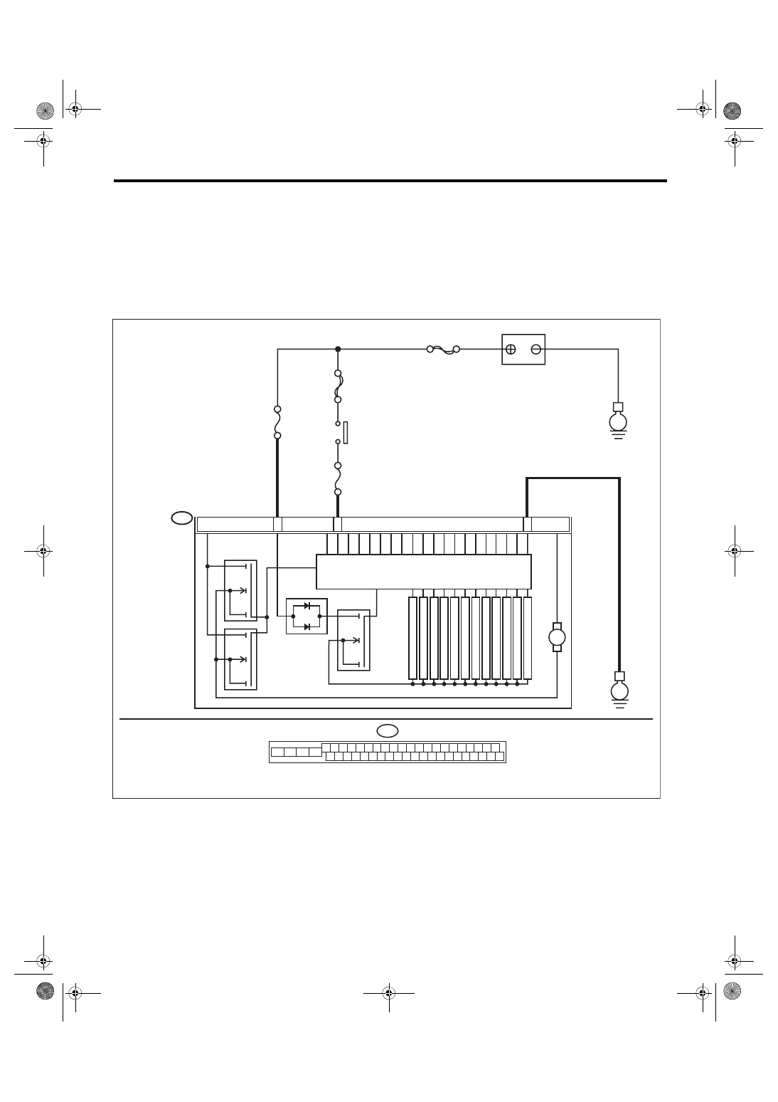
WIRING DIAGRAM:
Vehicle Dynamics Control System <Ref. to WI-67, Vehicle Dynamics Control System.>
B310
E
24
25
VDCCM & H/U
2
8
PUMP MO
T
OR
M
FL INLET
MAIN SBF
SBF-6
No.1
No.33
E
BATTERY
IGNITION
SWITCH
SOLENOID
V
AL
VE
FR INLET
RL INLET
RR INLET
FL OUTLET
FR OUTLET
RL OUTLET
RR OUTLET
P
R
IM
A
RY
C
U
T
S
E
C
O
N
D
A
RY
C
U
T
P
R
IM
A
RY
S
U
C
T
IO
N
MO
T
OR RELA
Y
VALVE RELAY
S
E
C
O
N
D
A
RY
S
U
C
T
IO
N
B310
4 5 6 7 8 9
26 27 28 29 30
2 3
1
31 32 33 34 35 36
10 11
14 15 16 17 18 19
37 38 39 40
12 13
41 42 43 44 45 46
20 21
23 24
22
25
VDC00466