Subaru Impreza 3 / Impreza WRX / Impreza WRX STI. Manual - part 541
VDC(diag)-63
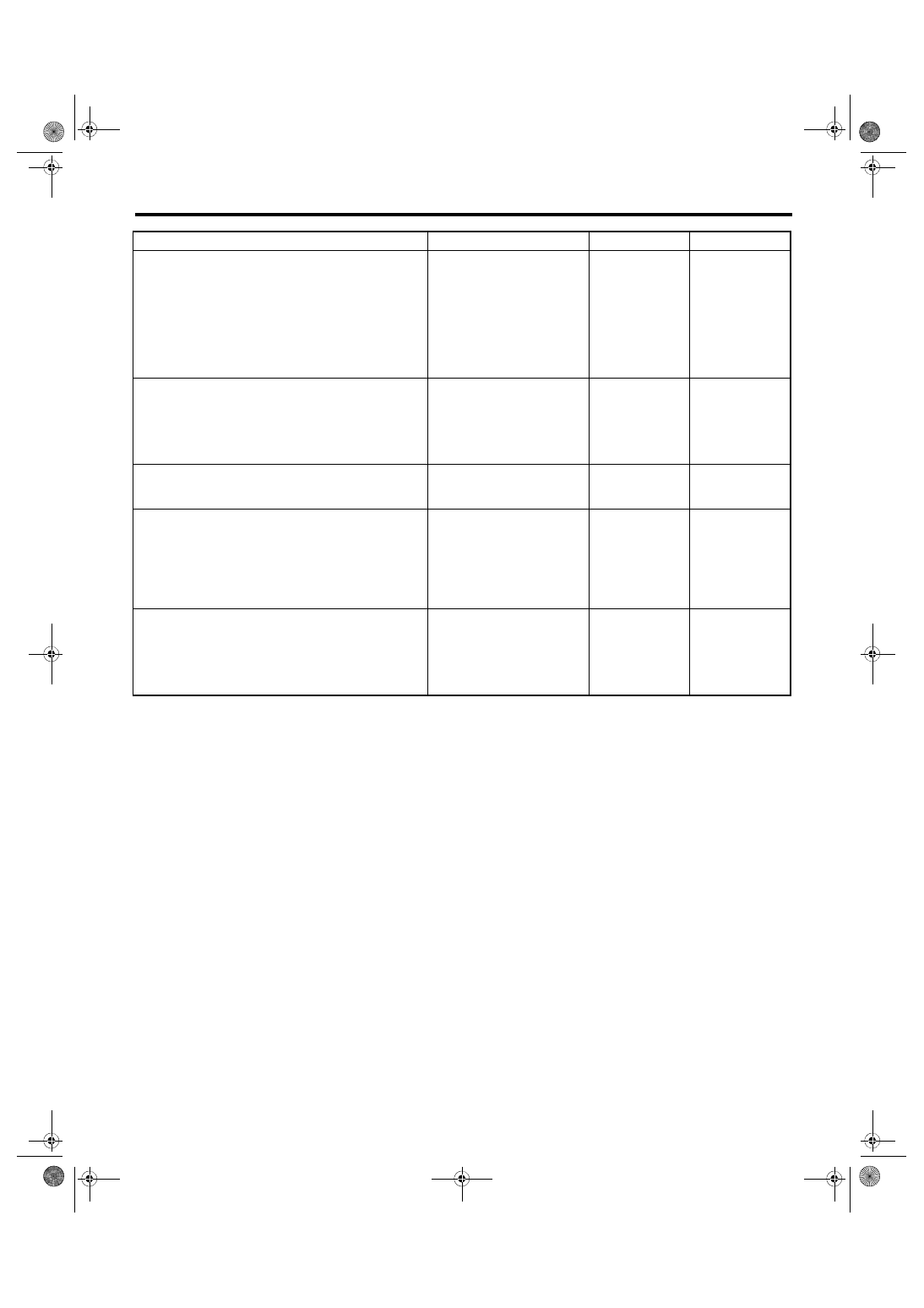
Diagnostic Procedure with Diagnostic Trouble Code (DTC)
VEHICLE DYNAMICS CONTROL (VDC) (DIAGNOSTICS)
Step
Check
Yes
No
1
CHECK VDCCM&H/U INPUT VOLTAGE.
1) Turn the ignition switch to OFF.
2) Disconnect the connector from the
VDCCM&H/U.
3) Run the engine at idle.
4) Measure the voltage between VDCCM&H/U
connector and chassis ground.
Connector & terminal
(B310) No. 28 (+) — Chassis ground (–):
Is the voltage 10 — 15 V?
Repair the power
supply circuit.
2
CHECK VDCCM&H/U GROUND CIRCUIT.
1) Turn the ignition switch to OFF.
2) Measure the resistance between
VDCCM&H/U connector and chassis ground.
Connector & terminal
(B310) No. 25 — Chassis ground:
Is the resistance less than 10
Ω?
Repair the
VDCCM&H/U
ground harness.
3
CHECK POOR CONTACT OF CONNEC-
TORS.
Is there poor contact of connec-
tor between generator, battery
and VDCCM&H/U?
Repair the connec-
tor.
4
CHECK VDCCM&H/U.
1) Connect all connectors.
2) Clear the memory. <Ref. to VDC(diag)-27,
Clear Memory Mode.>
3) Perform the Inspection Mode. <Ref. to
VDC(diag)-26, Inspection Mode.>
4) Read the DTC.
Is the same DTC displayed?
Replace the
VDCCM&H/U.
<Ref. to VDC-8,
VDC Control Mod-
ule and Hydraulic
Control Unit
(VDCCM&H/U).>
5
CHECK OTHER DTC DETECTION.
Is any other DTC displayed?
Temporary poor
contact occurs.