Subaru Impreza 3 / Impreza WRX / Impreza WRX STI. Manual - part 542


  Index      Subaru     Subaru Impreza 3 / Impreza WRX / Impreza WRX STI - service repair manual 2008-2014 year


Search            


Content   ..  540  541  542  543   ..


Subaru Impreza 3 / Impreza WRX / Impreza WRX STI. Manual - part 542


VDC(diag)-67

Diagnostic Procedure with Diagnostic Trouble Code (DTC)

VEHICLE DYNAMICS CONTROL (VDC) (DIAGNOSTICS)

Y: DTC C0042 POWER SUPPLY VOLTAGE FAILURE

DTC DETECTING CONDITION:

Improper VDCCM&H/U power supply voltage

TROUBLE SYMPTOM:

• ABS does not operate.

• EBD may not operate.

• VDC does not operate.
NOTE:

Warning lights go off if voltage returns.
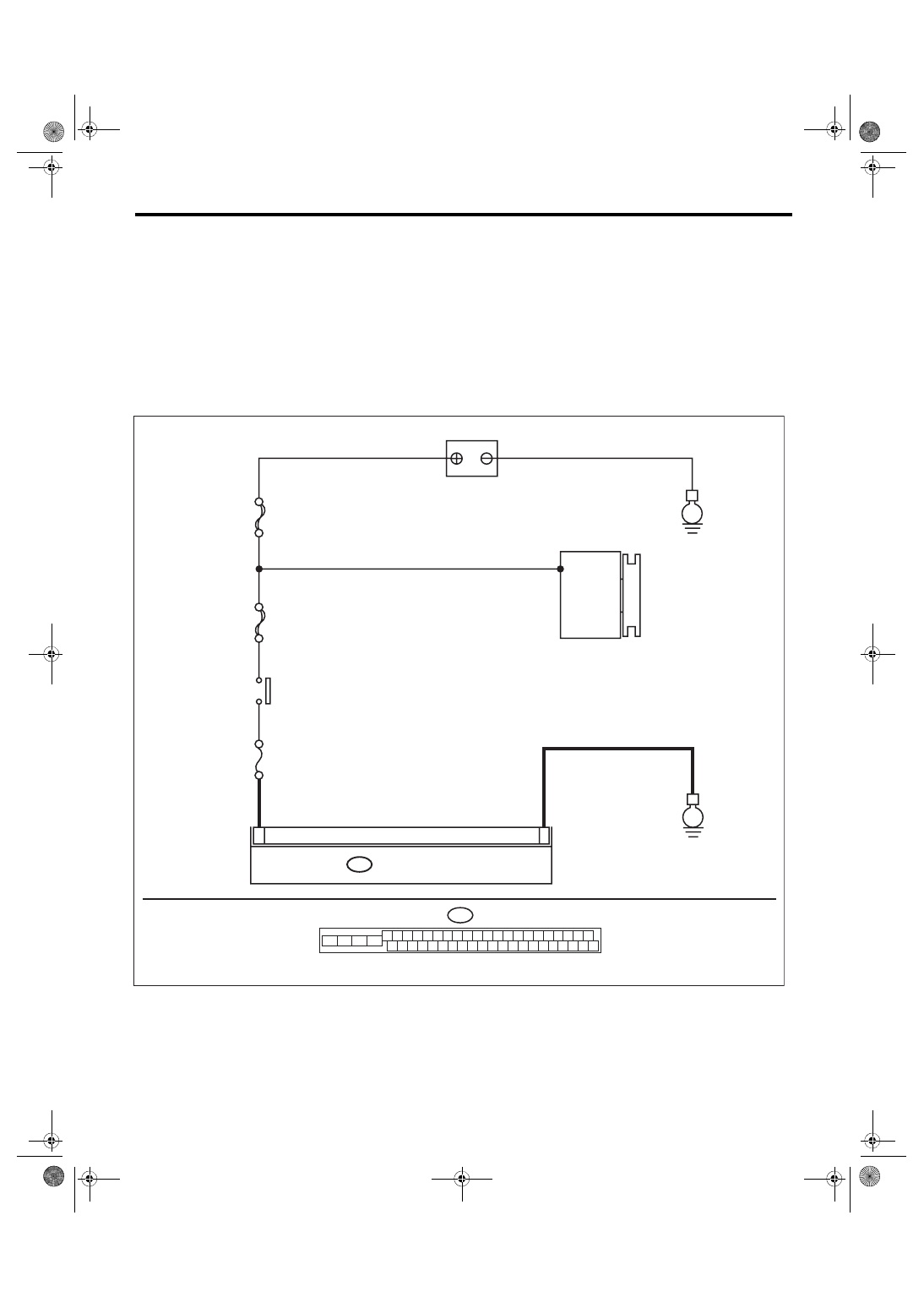
WIRING DIAGRAM:

Vehicle Dynamics Control System <Ref. to WI-67, Vehicle Dynamics Control System.>

MAIN SBF

SBF-6

No.33

B310

E

E

25

2

8

VDCCM & H/U

BATTERY

GENERATOR

IGNITION 

SWITCH

B310

4 5 6 7 8 9

26 27 28 29 30

2 3

1

31 32 33 34 35 36

10 11

14 15 16 17 18 19

37 38 39 40

12 13

41 42 43 44 45 46

20 21

23 24

22

25

VDC00463

VDC(diag)-68

Diagnostic Procedure with Diagnostic Trouble Code (DTC)

VEHICLE DYNAMICS CONTROL (VDC) (DIAGNOSTICS)

Step

Check

Yes

No

1

CHECK GENERATOR.
1) Start the engine.
2) Run the engine at idle after warming up.
3) Measure the voltage between generator ter-
minal B and chassis ground.

Terminals

Generator terminal B (+) — Chassis 
ground (–):

Is the voltage 10 — 15 V?

Go to step 

2.

Repair the genera-
tor.

2

CHECK BATTERY TERMINAL.
Turn the ignition switch to OFF.

Are the positive and negative 
battery terminals clamped 
tightly?

Go to step 

3.

Tighten the termi-
nal.

3

CHECK VDCCM&H/U INPUT VOLTAGE.
1) Disconnect the connector from the 
VDCCM&H/U.
2) Run the engine at idle.
3) Operate devices such as headlights, air 
conditioner, defogger, etc. which produce an 
electrical load.
4) Measure the voltage between VDCCM&H/U 
connector and chassis ground.

Connector & terminal

(B310) No. 28 (+) — Chassis ground (–):

Is the voltage 10 — 15 V?

Go to step 

4.

Repair the power 
supply circuit.

4

CHECK VDCCM&H/U GROUND CIRCUIT.
1) Turn the ignition switch to OFF.
2) Measure the resistance between 
VDCCM&H/U connector and chassis ground.

Connector & terminal

(B310) No. 25 — Chassis ground:

Is the resistance less than 10 

Ω?

Go to step 

5.

Repair the 
VDCCM&H/U 
ground harness.

5

CHECK POOR CONTACT OF CONNEC-
TORS.

Is there poor contact of connec-
tor between generator, battery 
and VDCCM&H/U?

Repair the connec-
tor.

Go to step 

6.

6

CHECK VDCCM&H/U.
1) Connect all connectors.
2) Clear the memory. <Ref. to VDC(diag)-27, 
Clear Memory Mode.>
3) Perform the Inspection Mode. <Ref. to 
VDC(diag)-26, Inspection Mode.>
4) Read the DTC.

Is the same DTC displayed?

Replace the 
VDCCM only. 
<Ref. to VDC-12, 
REPLACEMENT, 
VDC Control Mod-
ule and Hydraulic 
Control Unit 
(VDCCM&H/U).>

Go to step 

7.

7

CHECK OTHER DTC DETECTION.

Is any other DTC displayed?

Perform the diag-
nosis according to 
DTC. <Ref. to 
VDC(diag)-48, List 
of Diagnostic Trou-
ble Code (DTC).>

Temporary poor 
contact occurs.

VDC(diag)-69

Diagnostic Procedure with Diagnostic Trouble Code (DTC)

VEHICLE DYNAMICS CONTROL (VDC) (DIAGNOSTICS)

Z: DTC C0045 INCORRECT VDC CONTROL MODULE SPECIFICATIONS

DTC DETECTING CONDITION:

Different control module specification

TROUBLE SYMPTOM:

• ABS does not operate.

• VDC does not operate.
NOTE:

When parameter selection for VDCCM is improper, this DTC may be memorized.

Step

Check

Yes

No

1

CHECK VDCCM REPLACEMENT HISTORY. Is there history of VDCCM 

replacement by itself?

Go to step 

2.

Go to step 

3.

2

CHECK VDCCM IDENTIFICATION SYMBOL.
Check the identification symbol of the seal 
attached on the side of the VDCCM. <Ref. to 
VDC-2, SPECIFICATION, General Descrip-
tion.>

Is the identification symbol cor-
rect?

Go to step 

4.

Replace the 
VDCCM only. 
<Ref. to VDC-12, 
REPLACEMENT, 
VDC Control Mod-
ule and Hydraulic 
Control Unit 
(VDCCM&H/U).>

3

CHECK VDCCM&H/U IDENTIFICATION 
SYMBOL.
Check the identification symbol stamped on the 
upper part of the H/U. <Ref. to VDC-2, SPECI-
FICATION, General Description.>

Is the identification symbol cor-
rect?

Go to step 

4.

Replace the 
VDCCM&H/U. 
<Ref. to VDC-8, 
VDC Control Mod-
ule and Hydraulic 
Control Unit 
(VDCCM&H/U).>

4

CHECK PARAMETER SELECTED IN VDC-
CM.
<Ref. to VDC(diag)-21, PARAMETER CHECK, 
OPERATION, Subaru Select Monitor.>

Does the parameter registered 
in the VDCCM match the rele-
vant vehicle?

Go to step 

5.

Select and register 
the correct param-
eter. <Ref. to 
VDC(diag)-21, 
PARAMETER 
SELECTION, 
OPERATION, Sub-
aru Select Moni-
tor.>

5

CHECK ECM SPECIFICATION.
Check the ECM specification.

Is the specification of ECM 
same as vehicle specification?

Go to step 

6.

Replace the ECM. 
<Ref. to FU(STI)-
59, Engine Control 
Module (ECM).> 
<Ref. to FU(w/o 
STI)-57, Engine 
Control Module 
(ECM).>

6

CHECK VDCCM&H/U.
1) Connect all connectors.
2) Clear the memory. <Ref. to VDC(diag)-27, 
Clear Memory Mode.>
3) Perform the Inspection Mode. <Ref. to 
VDC(diag)-26, Inspection Mode.>
4) Read the DTC.

Is the same DTC displayed?

Replace the 
VDCCM only. 
<Ref. to VDC-12, 
REPLACEMENT, 
VDC Control Mod-
ule and Hydraulic 
Control Unit 
(VDCCM&H/U).>

Go to step 

7.

7

CHECK OTHER DTC DETECTION.

Is any other DTC displayed?

Perform the diag-
nosis according to 
DTC. <Ref. to 
VDC(diag)-48, List 
of Diagnostic Trou-
ble Code (DTC).>

It results from a 
temporary noise 
interference.

VDC(diag)-70

Diagnostic Procedure with Diagnostic Trouble Code (DTC)

VEHICLE DYNAMICS CONTROL (VDC) (DIAGNOSTICS)

AA:DTC C0047 CAN COMMUNICATION

DTC DETECTING CONDITION:

CAN communication line circuit is open or shorted.

TROUBLE SYMPTOM:

• ABS does not operate.

• VDC does not operate.

Step

Check

Yes

No

1

CHECK LAN SYSTEM.
Perform the diagnosis for LAN system. <Ref. to 
LAN(diag)-2, Basic Diagnostic Procedure.>

Is there any fault in LAN sys-
tem?

Perform the diag-
nosis according to 
DTC for LAN sys-
tem. <Ref. to 
LAN(diag)-32, List 
of Diagnostic Trou-
ble Code (DTC).>

Go to step 

2.

2

CHECK POOR CONTACT OF CONNEC-
TORS.

Is there poor contact of 
VDCCM&H/U connector?

Repair the connec-
tor.

Go to step 

3.

3

CHECK OUTPUT OF STEERING ANGLE 
SENSOR WITH SUBARU SELECT MONI-
TOR.
1) Select “Current Data Display & Save” on the 
Subaru Select Monitor. <Ref. to VDC(diag)-19, 
READ CURRENT DATA, OPERATION, Subaru 
Select Monitor.>
2) Check the «Steer Angle Sensor Op».

Does the output signal change? Go to step 

4.

Check output of 
the steering angle 
sensor. <Ref. to 
VDC(diag)-88, 
DTC C0071 
STEER ANGLE 
SENSOR OP, 
Diagnostic Proce-
dure with Diagnos-
tic Trouble Code 
(DTC).>

4

CHECK OUTPUT OF YAW RATE & G SEN-
SOR WITH SUBARU SELECT MONITOR.
1) Select “Current Data Display & Save” on the 
Subaru Select Monitor. <Ref. to VDC(diag)-19, 
READ CURRENT DATA, OPERATION, Subaru 
Select Monitor.>
2) Check the «Yaw Rate Sensor Output».

Does the output signal change? Go to step 

5.

Check output of 
the yaw rate & G 
sensor. <Ref. to 
VDC(diag)-98, 
DTC C0072 YAW 
RATE SENSOR 
COMMUNICA-
TION, Diagnostic 
Procedure with 
Diagnostic Trouble 
Code (DTC).>

5

CHECK VDCCM&H/U.
1) Connect all connectors.
2) Clear the memory. <Ref. to VDC(diag)-27, 
Clear Memory Mode.>
3) Perform the Inspection Mode. <Ref. to 
VDC(diag)-26, Inspection Mode.>
4) Read the DTC.

Is the same DTC displayed?

Replace the 
VDCCM only. 
<Ref. to VDC-12, 
REPLACEMENT, 
VDC Control Mod-
ule and Hydraulic 
Control Unit 
(VDCCM&H/U).>

Temporary poor 
contact occurs.


Content   ..  540  541  542  543   ..