Subaru Impreza 3 / Impreza WRX / Impreza WRX STI. Manual - part 531


  Index      Subaru     Subaru Impreza 3 / Impreza WRX / Impreza WRX STI - service repair manual 2008-2014 year


Search            


Content   ..  529  530  531  532   ..


Subaru Impreza 3 / Impreza WRX / Impreza WRX STI. Manual - part 531


VDC(diag)-23

Subaru Select Monitor

VEHICLE DYNAMICS CONTROL (VDC) (DIAGNOSTICS)

3

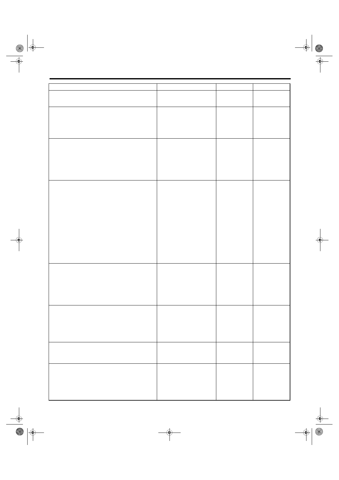
CHECK BATTERY TERMINAL.

Is there poor contact at battery 
terminal?

Repair or tighten 
the battery termi-
nal.

Go to step 

4.

4

CHECK SUBARU SELECT MONITOR COM-
MUNICATION.
1) Turn the ignition switch to ON.
2) Using the Subaru Select Monitor, check 
whether communication to other systems can 
be executed normally.

Is the system name displayed 
on Subaru Select Monitor?

Go to step 

8.

Go to step 

5.

5

CHECK SUBARU SELECT MONITOR COM-
MUNICATION.
1) Turn the ignition switch to OFF.
2) Disconnect the VDCCM&H/U connector.
3) Turn the ignition switch to ON.
4) Check whether communication to other sys-
tems can be executed normally.

Is the system name displayed 
on Subaru Select Monitor?

Replace the 
VDCCM only. 
<Ref. to VDC-12, 
REPLACEMENT, 
VDC Control Mod-
ule and Hydraulic 
Control Unit 
(VDCCM&H/U).>

Go to step 

6.

6

CHECK HARNESS CONNECTOR BETWEEN 
EACH CONTROL MODULE AND DATA LINK 
CONNECTOR.
1) Turn the ignition switch to OFF.
2) Disconnect the connectors from ECM, air-
bag CM, TPMS & keyless entry CM, DCCD CM 
(6MT model only) and body integrated unit.
CAUTION:

When disconnecting the connector from air-
bag  CM,  always  follow  the  precautions  on
AB section. <Ref. to AB-5, CAUTION, Gener-
al Description.>
3) Measure the resistance between data link 
connector and chassis ground.

Connector & terminal

(B40) No. 7 — Chassis ground:

Is the resistance 1 MΩ or 
more?

Go to step 

7.

Repair the harness 
and connector 
between each con-
trol module and 
data link connec-
tor.

7

CHECK HARNESS CONNECTOR BETWEEN 
VDCCM&H/U AND DATA LINK CONNEC-
TOR.
1) Turn the ignition switch to ON.
2) Measure the voltage between data link con-
nector and chassis ground.

Connector & terminal

(B40) No. 7 (+) — Chassis ground (–):

Is the voltage less than 1 V?

Go to step 

8.

Repair the harness 
and connector 
between each con-
trol module and 
data link connec-
tor.

8

CHECK HARNESS CONNECTOR BETWEEN 
VDCCM&H/U AND DATA LINK CONNEC-
TOR.
Measure the resistance between VDCCM&H/U 
connector and data link connector.

Connector & terminal

(B310) No. 7 — (B40) No. 7:

Is the resistance less than 1 Ω? Go to step 

9.

Repair harness 
and connector 
between 
VDCCM&H/U and 
data link connec-
tor.

9

CHECK INSTALLATION OF VDCCM&H/U 
CONNECTOR.
Turn the ignition switch to OFF.

Is the VDCCM&H/U connector 
inserted into VDCCM&H/U until 
the clamp locks onto it?

Go to step 

10.

Insert 
VDCCM&H/U 
connector into 
VDCCM&H/U.

10

CHECK POWER SUPPLY CIRCUIT.
1) Turn the ignition switch to ON. (engine OFF)
2) Measure the ignition power supply voltage 
between VDCCM&H/U connector and chassis 
ground.

Connector & terminal

(B310) No. 28 (+) — Chassis ground (–):

Is the voltage 10 — 15 V?

Go to step 

11.

Repair the open 
circuit and poor 
contact of the con-
nector between 
VDCCM&H/U and 
battery.

Step

Check

Yes

No

VDC(diag)-24

Subaru Select Monitor

VEHICLE DYNAMICS CONTROL (VDC) (DIAGNOSTICS)

11

CHECK HARNESS CONNECTOR BETWEEN 
VDCCM&H/U AND CHASSIS GROUND.
1) Turn the ignition switch to OFF.
2) Disconnect the connector from the 
VDCCM&H/U.
3) Measure the resistance of harness between 
VDCCM&H/U connector and chassis ground.

Connector & terminal

(B310) No. 25 — Chassis ground:

Is the resistance less than 10 

Ω?

Go to step 

12.

Repair the open 
circuit of 
VDCCM&H/U 
ground harness 
and poor contact of 
connector.

12

CHECK POOR CONTACT OF CONNECTOR. Is there poor contact of control 

module power supply, ground 
circuit and data link connector?

Repair the connec-
tor.

Replace the 
VDCCM only. 
<Ref. to VDC-12, 
REPLACEMENT, 
VDC Control Mod-
ule and Hydraulic 
Control Unit 
(VDCCM&H/U).>

Step

Check

Yes

No

VDC(diag)-25

Read Diagnostic Trouble Code (DTC)

VEHICLE DYNAMICS CONTROL (VDC) (DIAGNOSTICS)

7. Read Diagnostic Trouble 

Code (DTC)

A: OPERATION

1) On «Main Menu» display, select {Each System

Check}.

2) On  «System  Selection  Menu»  display,  select

{Brake Control System}.

3) Click the [OK] button after {VDC} is displayed.

4) On  «Brake  Control  Diagnosis»  display,  select

{Diagnostic Code(s) Display}.

5) Record the DTC and data.
NOTE:

• For detailed operation procedures, refer to “PC

application help for Subaru Select Monitor”.

• For details concerning DTCs, refer to “List of Di-

agnostic  Trouble  Code  (DTC)”.  <Ref.  to  VDC(di-

ag)-48, List of Diagnostic Trouble Code (DTC).>

• Up to 3 DTCs are displayed in the order of detec-

tion.

• If a particular DTC is not stored in memory prop-

erly at the occurrence of problem (due to a drop in

VDCCM&H/U power supply etc.), the DTC suffixed

with a question mark “?” is displayed on Subaru Se-

lect Monitor display screen. This shows it may be

an unreliable reading.

Display

Contents to be displayed

(Current)

The current DTC is displayed on Subaru 
Select Monitor display screen.

(Before 1)

The latest DTC from the history of previ-
ous problems is displayed on Subaru 
Select Monitor display screen.

(Before 2)

The second latest DTC from the history 
of previous problems is displayed on the 
Subaru Select Monitor display screen.

(Before 3)

The third latest DTC from the history of 
previous problems is displayed on Sub-
aru Select Monitor display screen.

VDC(diag)-26

Inspection Mode

VEHICLE DYNAMICS CONTROL (VDC) (DIAGNOSTICS)

8. Inspection Mode

A: PROCEDURE

Reproduce  the  malfunction  occurrence  condition

as much as possible.

Drive the vehicle at least ten minutes.
NOTE:

Make sure the vehicle is not dragged to one side

under usual driving condition.


Content   ..  529  530  531  532   ..