Subaru Impreza 3 / Impreza WRX / Impreza WRX STI. Manual - part 529
VDC(diag)-15
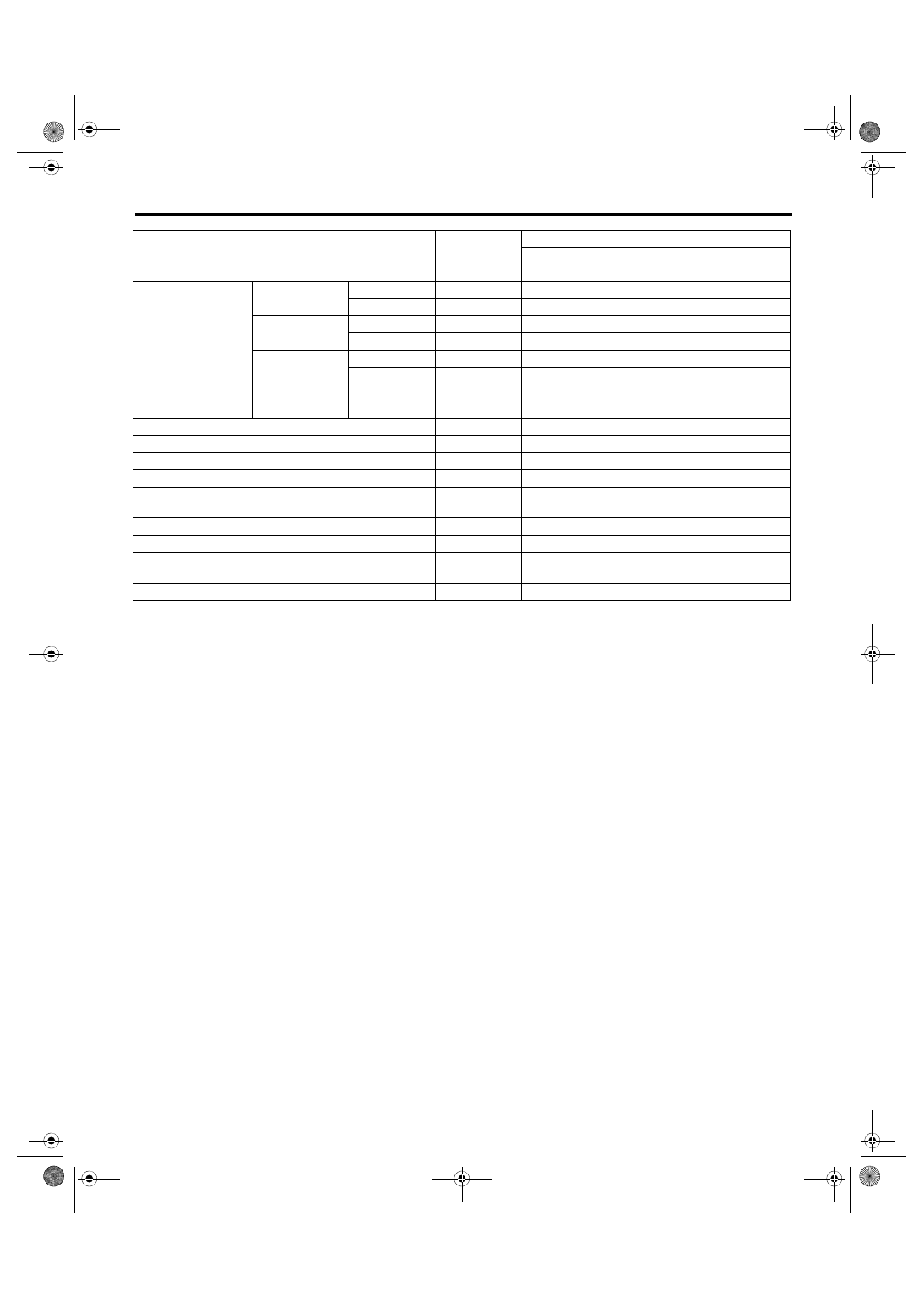
Control Module I/O Signal
VEHICLE DYNAMICS CONTROL (VDC) (DIAGNOSTICS)
Contents
Terminal No.
(+) — (–)
Input/Output signal
Measured value and measuring conditions
Power supply
28 — 25
10 — 15 V when the ignition switch is ON.
ABS wheel speed
sensor
Front LH wheel
Power supply
26 — 25
4.5 — 16.5 V
Signal
1
5.9 — 16.8 mA: Rectangle waveform
Front RH wheel
Power supply
5 — 25
4.5 — 16.5 V
Signal
6
5.9 — 16.8 mA: Rectangle waveform
Rear LH wheel
Power supply
2 — 25
4.5 — 16.5 V
Signal
27
5.9 — 16.8 mA: Rectangle waveform
Rear RH wheel
Power supply
3 — 25
4.5 — 16.5 V
Signal
4
5.9 — 16.8 mA: Rectangle waveform
CAN communication line (+)
35
2.5 — 1.5 V pulse signal
CAN communication line (–)
10
3.5 — 2.5 V pulse signal
Valve relay power supply
24 — 25
10 — 15 V when the ignition switch is ON.
Motor relay power supply
23 — 22
10 — 15 V when the ignition switch is ON.
Stop light switch
30 — 25
1.5 V or less when the stop light is OFF; otherwise,
10 — 15 V when the stop light is ON.
Subaru Select Monitor
7 — 25
0 ←→ 12 V pulse (in communication)
Vehicle speed output signal
33
0 ←→ 5 V pulse
VDC OFF switch
31 — 25
1 Ω or less when the switch is ON; 1 MΩ or more
when the switch is OFF.
Ground
25
—