Subaru Impreza 3 / Impreza WRX / Impreza WRX STI. Manual - part 527
VDC(diag)-7
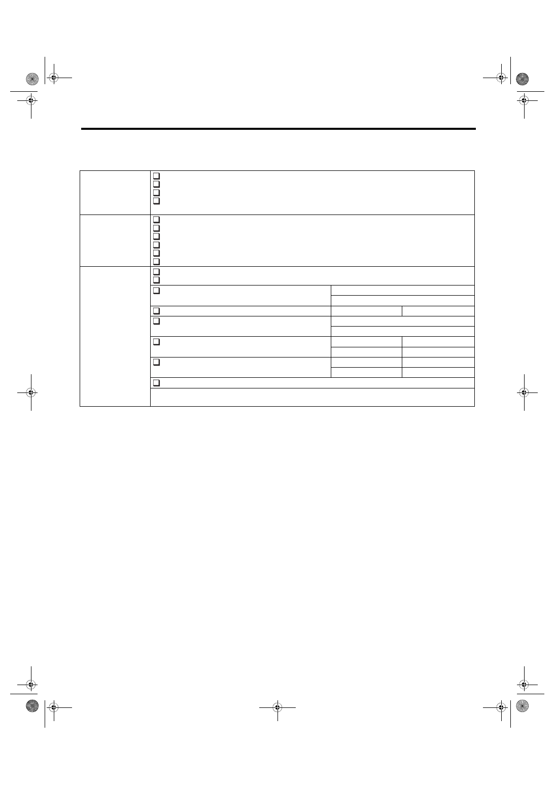
Check List for Interview
VEHICLE DYNAMICS CONTROL (VDC) (DIAGNOSTICS)
4. STATE OF VDC OFF INDICATOR LIGHT
NOTE:
This check list for interview is applied to 5MT model.
VDC OFF indicator
light comes on.
Always
Sometimes
Only once
Does not illuminate
• When/How long does it illuminate?
Ignition key position
LOCK
ACC
ON (before starting engine)
START
ON (after starting engine, engine is running)
ON (after starting engine, engine is at a standstill)
Timing
Immediately after turning the ignition switch to ON
Immediately after turning the ignition switch to START
While accelerating
—
km/h
—
MPH
While driving at a constant speed
km/h
MPH
While decelerating
—
km/h
—
MPH
When turning to the right
Steering angle:
deg
Steering time:
Sec.
When turning to the left
Steering angle:
deg
Steering time:
Sec.
When other electrical parts are operating
• Part name:
• Operating condition: