Subaru Impreza 3 / Impreza WRX / Impreza WRX STI. Manual - part 482
TPM(diag)-5
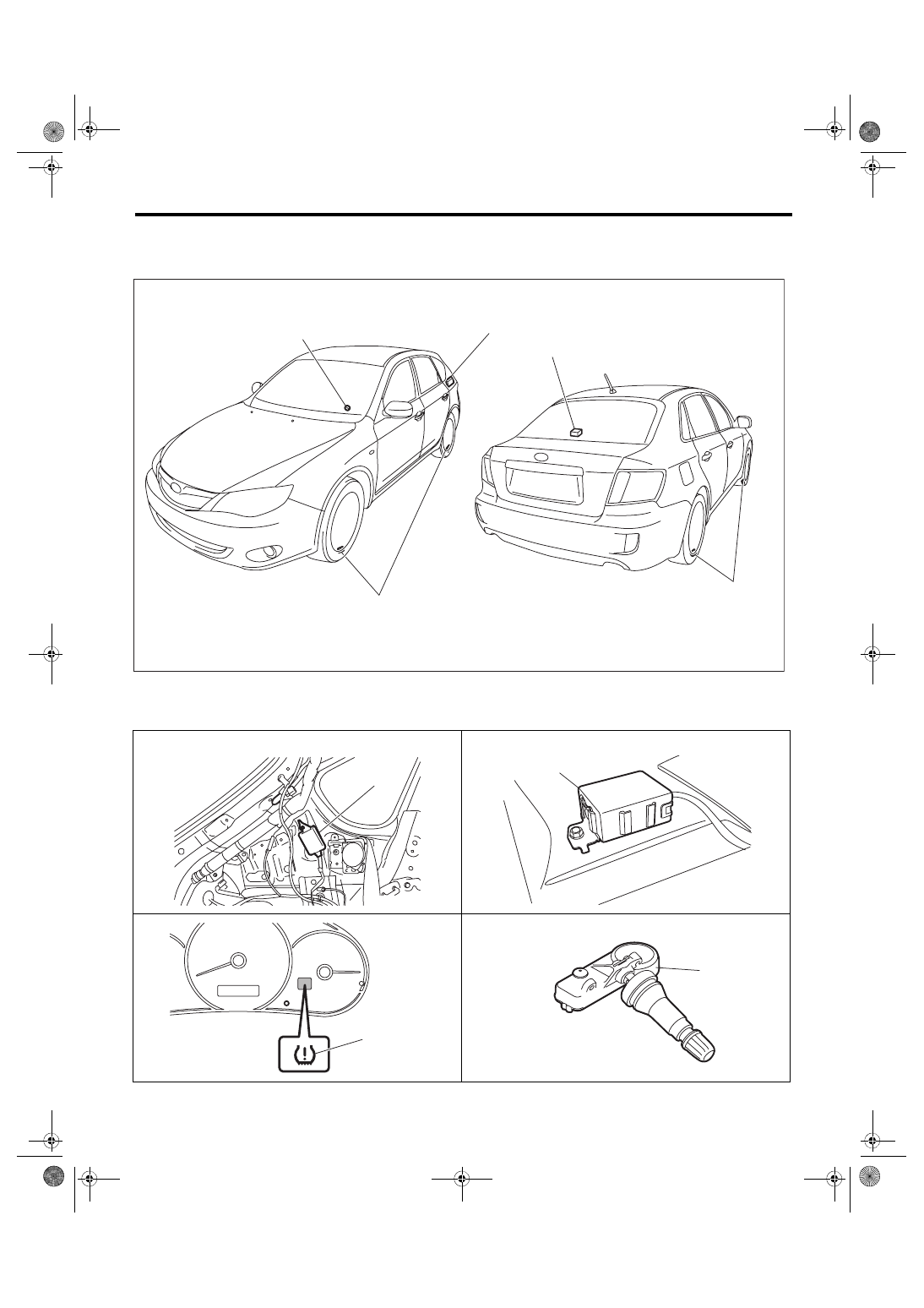
Electrical Component Location
TIRE PRESSURE MONITORING SYSTEM (DIAGNOSTICS)
3. Electrical Component Location
A: LOCATION
(1)
TPMS & keyless entry control
module
(2)
Tire pressure warning light
(3)
Snap-in type transmitter
• 5 DOOR MODEL
• 4 DOOR MODEL
TPM00075
(1)
(1)
(2)
(3)
(3)
TPM00076
(1)
TPM00077
(1)
TPM00048
(2)
(3)
TPM00049