Subaru Impreza 3 / Impreza WRX / Impreza WRX STI. Manual - part 483


  Index      Subaru     Subaru Impreza 3 / Impreza WRX / Impreza WRX STI - service repair manual 2008-2014 year


Search            


Content   ..  481  482  483  484   ..


Subaru Impreza 3 / Impreza WRX / Impreza WRX STI. Manual - part 483


TPM(diag)-9

Subaru Select Monitor

TIRE PRESSURE MONITORING SYSTEM (DIAGNOSTICS)

4. REGISTER TRANSMITTER ID

Perform the registration procedure of the transmit-

ter in the following cases:

• Transmitter replaced.

• TPMS & keyless entry control module replaced.
NOTE:

• If registration of the transmitter ID is not possible

after  2  attempts,  replace  TPMS  &  keyless  entry

control module. <Ref. to WT-8, TPMS & KEYLESS

ENTRY  CONTROL  MODULE,  REMOVAL,  Tire

Pressure  Monitoring  System.>  <Ref.  to  WT-9,

TPMS & KEYLESS ENTRY CONTROL MODULE,

INSTALLATION,  Tire  Pressure  Monitoring  Sys-

tem.>

• During the registration, turn the ignition switch to

OFF and end the Subaru Select Monitor. Or if the

registration is not performed for 5 minutes or more,

the registration mode is cancelled.

• When rotating tires, there is no affect on the per-

formance or functions of the tire pressure monitor-

ing control module even if the transmitter (ID) is not

registered, however, the tire position displayed on

the Subaru Select Monitor will be incorrect.

1) Adjust all tire pressures to the specifications.

2) Connect  Subaru  Select  Monitor  and  select  the

{Each System Check} on the «Main Menu».

3) On  «System  Selection  Menu»  display,  select

{Tire pressure monitor}.

4) After  the  {Tire  pressure  monitor}  is  displayed,

select [OK].

5) On  «Tire  pressure  monitor  diagnosis»  display,

select {Transmitter ID regist confirm}.

6) {ID registration mode When execute Registered

ID is deleted. Continue?} is displayed, select [OK].

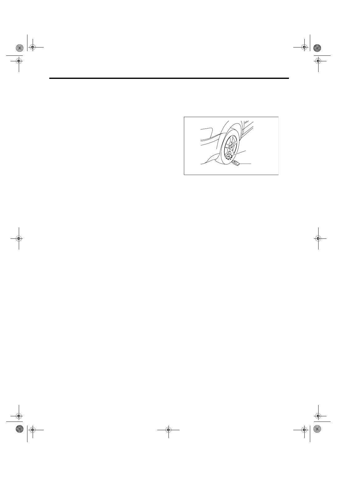
7) Contact  the  transmitter  registration  tool  to  the

side wall area near the air valve on the front left tire,

and press the switch. The transmitter ID is sent to

the TPMS & keyless entry control module. (At this

time, the tire pressure warning light blinks to con-

firm that the registration has started.)

NOTE:

• The  registration  order  of  transmitter  ID  is  not

specified.

• The transmitter registration tool is used by touch-

ing the side wall area near the transmitter.

• If  registration  procedure  stop  in  the  halfway

(turning ignition switch to OFF, wrong registration

order, etc), proceed from step 5).

8) When ID registration is completed, the tire pres-

sure  warning  light  remains  lit  for  approximately  2

seconds,  to  end  the  registration.  Switch  to  the

screen displaying the transmitter ID on the Subaru

Select Monitor display. <Ref. to TPM(diag)-9, DIS-

PLAY TRANSMITTER (ID), OPERATION, Subaru

Select Monitor.>

9) Check  the  transmitter  ID  that  was  registered,

then perform a driving test. <Ref. to TPM(diag)-13,

PROCEDURE, Inspection Mode.>

5. DISPLAY TRANSMITTER (ID)

1) On «Main Menu» display, select {Each System

Check}.

2) On  «System  Selection  Menu»  display,  select

{Tire pressure monitor}.

3) After  the  {Tire  pressure  monitor}  is  displayed,

select [OK].

4) On  «Tire  pressure  monitor  diagnosis»  display,

select {Transmitter ID regist confirm}.

5) Select the {Transmitter ID monitor} and then se-

lect [OK] to display the transmitter ID.

(1) Air valve (transmitter)
(2) Transmitter registration tool

(1)

(2)

TPM00006

TPM(diag)-10

Subaru Select Monitor

TIRE PRESSURE MONITORING SYSTEM (DIAGNOSTICS)

B: INSPECTION

1. COMMUNICATION FOR INITIALIZING IMPOSSIBLE

DETECTING CONDITION:

Defective harness connector

TROUBLE SYMPTOM:

Communication is impossible between the TPMS & keyless entry control module and the Subaru Select

Monitor.

WIRING DIAGRAM:

Tire Pressure Monitoring System <Ref. to WI-71, WIRING DIAGRAM, Tire Pressure Monitoring System.>

Step

Check

Yes

No

1

CHECK IGNITION SWITCH.

Is the ignition switch ON?

Go to step 

2.

Turn the ignition 
switch to ON, and 
select TPM mode 
using Subaru 
Select Monitor.

2

CHECK BATTERY.

Is the voltage 11 V or more?

Go to step 

3.

Charge or replace 
the battery.

3

CHECK BATTERY TERMINAL.

Is there poor contact at battery 
terminal?

Repair or tighten 
the battery termi-
nal.

Go to step 

4.

4

CHECK SUBARU SELECT MONITOR COM-
MUNICATION.
1) Turn the ignition switch to ON.
2) Using the Subaru Select Monitor, check 
whether communication to other systems can 
be executed normally.

Is the system name displayed 
on Subaru Select Monitor?

Go to step 

8.

Go to step 

5.

5

CHECK SUBARU SELECT MONITOR COM-
MUNICATION.
1) Turn the ignition switch to OFF.
2) Disconnect the TPMS & keyless entry con-
trol module.
3) Turn the ignition switch to ON.
4) Check whether communication to other sys-
tems can be executed normally.

Is the system name displayed 
on Subaru Select Monitor?

Replace the TPMS 
& keyless entry 
control module. 
<Ref. to WT-8, 
TPMS & KEY-
LESS ENTRY 
CONTROL MOD-
ULE, REMOVAL, 
Tire Pressure 
Monitoring Sys-
tem.>

Go to step 

6.

R221

1 2 3 4 5 6
7 8 9 10 11 12

B99

1 2

3 4 5

6 7 8 9 10 11 12

B440

B435

1 2 3 4 5

B40

1 2 3 4 5 6 7 8

9 10 11 12 13 14 15 16

2

3

B435

B440

8

5

16

7

B40

B99

R3

R221

12

4

6

TPM00078

TO POWER SUPPLY CIRCUIT

MB-27

M/B FUSE NO. 13

(B)

FB-11

M/B FUSE NO. 8

(B)

FB-48

F/B FUSE NO. 4

(IG)

TPMS & KEYLESS ENTRY CM

DATA LINK 

CONNECTOR

MULTI JOINT 

CONNECTOR

TPM(diag)-11

Subaru Select Monitor

TIRE PRESSURE MONITORING SYSTEM (DIAGNOSTICS)

6

CHECK HARNESS CONNECTOR BETWEEN 
EACH CONTROL MODULE AND DATA LINK 
CONNECTOR.
1) Turn the ignition switch to OFF.
2) Disconnect the TPMS & keyless entry con-
trol module.
3) Measure the resistance between data link 
connector and chassis ground.

Connector & terminal

(B40) No. 7 — Chassis ground:

Is the resistance 1 MΩ or 
more?

Go to step 

7.

Repair the harness 
and connector 
between each con-
trol module and 
data link connec-
tor.

7

CHECK OUTPUT SIGNAL TO TPMS & KEY-
LESS ENTRY CONTROL MODULE.
1) Turn the ignition switch to ON.
2) Measure the voltage between TPMS & key-
less entry control module and chassis ground.

Connector & terminal

(B40) No. 7 (+) — Chassis ground (–):

Is the voltage less than 1 V?

Go to step 

8.

Repair the harness 
and connector 
between each con-
trol module and 
data link connec-
tor.

8

CHECK HARNESS CONNECTOR BETWEEN 
TPMS & KEYLESS ENTRY CONTROL MOD-
ULE AND DATA LINK CONNECTOR.
1) Turn the ignition switch to OFF.
2) Measure the resistance between the TPMS 
& keyless entry control module connector and 
the data link connector.

Connector & terminal

(R221) No. 12 — (B40) No. 7:

Is the resistance less than 0.5 

Ω?

Go to step 

9.

Repair the harness 
and connector 
between TPMS & 
keyless entry con-
trol module and 
data link connec-
tor.

9

CHECK TPMS & KEYLESS ENTRY CON-
TROL MODULE CONNECTOR.

Is TPMS & keyless entry control 
module connector inserted until 
it locks?

Go to step 

10.

Insert the connec-
tor into the TPMS 
& keyless entry 
control module.

10

CHECK POWER SUPPLY CIRCUIT.
1) Turn the ignition switch to ON.
2) Measure the ignition power supply voltage 
between TPMS & keyless entry control module 
connector and chassis ground.

Connector & terminal

(R221) No. 4 (+) — Chassis ground (–):

Is the voltage 10 — 15 V?

Go to step 

11.

Repair open circuit 
of the harness 
between TPMS & 
keyless entry con-
trol module and 
battery.

11

CHECK HARNESS CONNECTOR BETWEEN 
TPMS & KEYLESS ENTRY CONTROL MOD-
ULE AND CHASSIS GROUND.
1) Turn the ignition switch to OFF.
2) Disconnect the connector from the TPMS & 
keyless entry control module.
3) Measure the resistance of harness between 
TPMS & keyless entry control module and 
chassis ground.

Connector & terminal

(R221) No. 5 — Chassis ground:

Is the resistance less than 0.5 

Ω?

Go to step 

12.

Repair open circuit 
of the harness of 
the TPMS & key-
less entry control 
module.

12

CHECK POOR CONTACT OF CONNECTOR. Is there poor contact of TPMS & 

keyless entry control module 
power supply, ground circuit 
and data link connector?

Repair the connec-
tor.

Replace the TPMS 
& keyless entry 
control module. 
<Ref. to WT-8, 
TPMS & KEY-
LESS ENTRY 
CONTROL MOD-
ULE, REMOVAL, 
Tire Pressure 
Monitoring Sys-
tem.>

Step

Check

Yes

No

TPM(diag)-12

Read Diagnostic Trouble Code (DTC)

TIRE PRESSURE MONITORING SYSTEM (DIAGNOSTICS)

6. Read Diagnostic Trouble 

Code (DTC)

A: OPERATION

For details about reading of DTCs, refer to “Subaru

Select Monitor”. <Ref. to TPM(diag)-7, Subaru Se-

lect Monitor.>


Content   ..  481  482  483  484   ..