Subaru Impreza 3 / Impreza WRX / Impreza WRX STI. Manual - part 477


  Index      Subaru     Subaru Impreza 3 / Impreza WRX / Impreza WRX STI - service repair manual 2008-2014 year


Search            


Content   ..  475  476  477  478   ..


Subaru Impreza 3 / Impreza WRX / Impreza WRX STI. Manual - part 477


RS-15

Front Lateral Link

REAR SUSPENSION

7. Front Lateral Link

A: REMOVAL

1) Lift  up  the  vehicle,  and  then  remove  the  rear

wheels.

2) Remove  the  rear  trailing  link.  <Ref.  to  RS-10,

REMOVAL, Rear Trailing Link.>

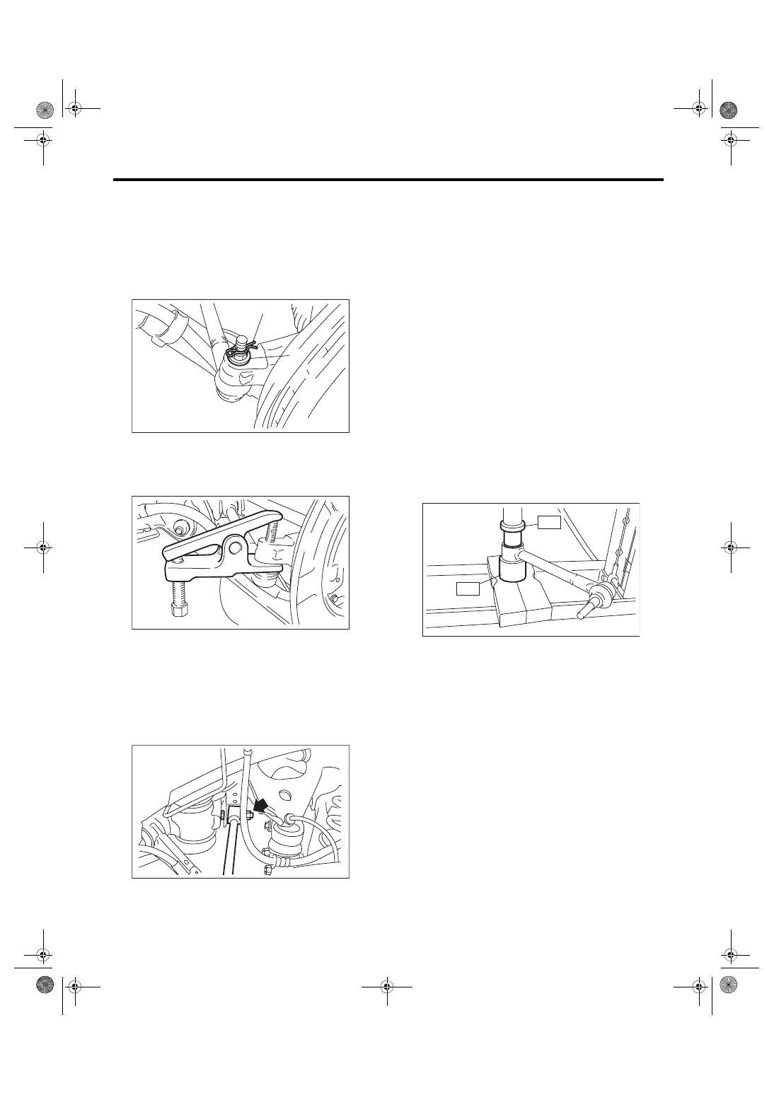
3) Remove the snap pin and nut.

4) Using a puller, remove the ball joint.

5) Scribe an alignment mark on the front lateral link

adjusting bolt and rear sub frame.

6) Remove the adjusting bolt, and remove the front

lateral link.
CAUTION:

When  removing the adjusting  bolt, make sure

to fix the bolt head in place when loosening the

nut.

B: INSTALLATION

CAUTION:

• Be sure to use a new self-locking nut.

• Always tighten the bushing in the state where

the vehicle is at curb weight and the wheels are

in full contact with the ground.

1) Install each part in the reverse order of removal.
Tightening torque:

Front lateral link — Sub frame

100 N·m (10.2 kgf-m, 73.8 ft-lb)

Front lateral link — Rear axle housing

60 N·m (6.1 kgf-m, 44.3 ft-lb)

2) Inspect the wheel alignment and adjust if neces-

sary.

C: INSPECTION

Visually check the front lateral link for damage and

deformation.

D: DISASSEMBLY

Using the ST A and ST B, press the bushing out.

ST A 20099AE000 INSTALLER & REMOVER

ST B 20099AE000 INSTALLER & REMOVER

E: ASSEMBLY

Using the ST A and ST B, press-fit the bushing.
CAUTION:

Make sure to press the bushing straight in.

ST A 20099AE000 INSTALLER & REMOVER

ST B 20099AE000 INSTALLER & REMOVER

(1) Snap pin
(2) Nut

(2)

(1)

RS-00189

RS-00190

RS-00262

ST-A

ST-B

RS-00192

RS-16

Rear Lateral Link

REAR SUSPENSION

8. Rear Lateral Link

A: REMOVAL

1) Lift  up  the  vehicle,  and  then  remove  the  rear

wheels.

2) Remove  the  nut  and  disconnect  the  stabilizer

link.

3) Remove the shock absorber lower bolt.

4) Remove the bolt, and remove rear lateral link.

B: INSTALLATION

CAUTION:

• Be sure to use a new self-locking nut.

• Always tighten the bushing in the state where

the vehicle is at curb weight and the wheels are

in full contact with the ground.

1) Install each part in the reverse order of removal.
Tightening torque:

Rear lateral link

80 N·m (8.2 kgf-m, 59.0 ft-lb)

Shock absorber

80 N·m (8.2 kgf-m, 59.0 ft-lb)

Stabilizer link

38 N·m (3.9 kgf-m, 28 ft-lb)

2) Inspect the wheel alignment and adjust if neces-

sary.

C: DISASSEMBLY

Using the ST A and ST B, press the bushing out.

ST A 20099AE010 INSTALLER & REMOVER

ST B 20099AE010 INSTALLER & REMOVER

D: ASSEMBLY

Using the ST A and ST B, press-fit the bushing.

ST A 20099AE010 INSTALLER & REMOVER

ST B 20099AE010 INSTALLER & REMOVER

E: INSPECTION

Visually check the rear lateral link for damage and

deformation.

RS-00263

RS-00083

ST-A

ST-B

RS-00083

ST-A

ST-B

RS-17

Rear Sub Frame

REAR SUSPENSION

9. Rear Sub Frame

A: REMOVAL

1) Lift  up  the  vehicle,  and  then  remove  the  rear

wheels.

2) Separate  the  front  exhaust  pipe  and  rear  ex-

haust pipe.

3) Remove the rear exhaust pipe and muffler.

4) Remove the propeller shaft. <Ref. to DS-11, RE-

MOVAL, Propeller Shaft.>

5) Remove the rear ABS wheel speed sensor from

the rear housing.

6) Remove the brake hose bracket from rear hous-

ing.

7) Remove  the  rear  disc  brake  caliper,  and  sus-

pend it from the shock absorber. (Disc brake mod-

el)

8) Remove the rear parking brake cable from the

parking brake assembly. <Ref. to PB-6, REMOV-

AL, Parking Brake Assembly (Rear Disc Brake).>

9) Disconnect  the  ABS  wheel  speed  sensor  con-

nector.

10) Remove the shock absorber lower bolt.

11) Support the sub frame using a jack.

12) Remove the support plate.

13) Remove the rear sub frame.

FU-03357

RS-00264

FU-03358

RS-00266

RS-00267

RS-00268

RS-00269

RS-18

Rear Sub Frame

REAR SUSPENSION

B: INSTALLATION

CAUTION:

• Be sure to use a new self-locking nut.

• Always tighten the bushing in the state where

the vehicle is at curb weight and the wheels are

in full contact with the ground.

1) Install each part in the reverse order of removal.
Tightening torque:

Refer to “COMPONENT” of “General Descrip-

tion” for the tightening torque. <Ref. to RS-3, 

COMPONENT, General Description.>

2) Inspect the wheel alignment and adjust if neces-

sary.

C: INSPECTION

Check  the  removed  parts  for  wear,  damage  and

crack, and repair or replace them if faulty.


Content   ..  475  476  477  478   ..