Subaru Impreza 3 / Impreza WRX / Impreza WRX STI. Manual - part 476
RS-11
Rear Trailing Link
REAR SUSPENSION
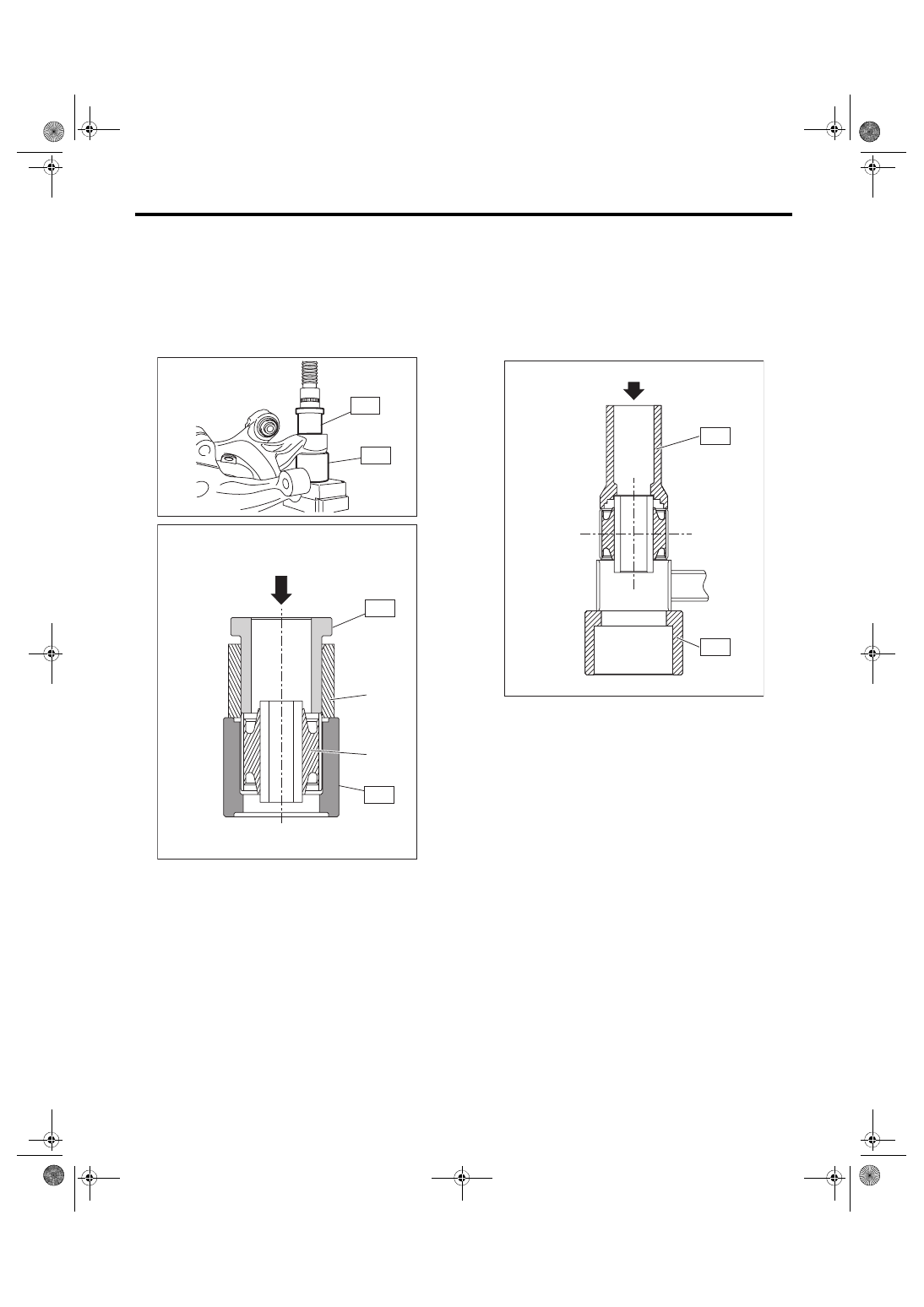
2. REAR HOUSING BUSHING
1) Remove the rear housing. <Ref. to DS-20, RE-
2) Using the ST and a hydraulic press, push out the
bushing.
ST 1 200099FG000 BUSHING REMOVER
ST 2 20099PA010
INSTALLER & REMOVER
(BASE)
D: ASSEMBLY
1. REAR TRAILING LINK BUSHING
Using the ST A and ST B, press-fit the bushing.
CAUTION:
Make sure to press the bushing straight in.
ST A 8998741000 INSTALLER
ST B 20299AG010 BASE
(1) Rear housing
(2) Bushing
DS-00458
ST1
ST2
ST1
ST2
(1)
(2)
DS-00459
ST-A
ST-B
RS-00256