Subaru Impreza 3 / Impreza WRX / Impreza WRX STI. Manual - part 453
6MT(diag)-23
Diagnostic Procedure with Diagnostic Trouble Code (DTC)
MANUAL TRANSMISSION AND DIFFERENTIAL (DIAGNOSTICS)
D: DTC P1769 YAW RATE & LATERAL G SENSOR MALFUNCTION
DIAGNOSIS:
Malfunction information transmitted from the yaw rate & G sensor
TROUBLE SYMPTOM:
A tendency to understeer occurs during high speed cornering.
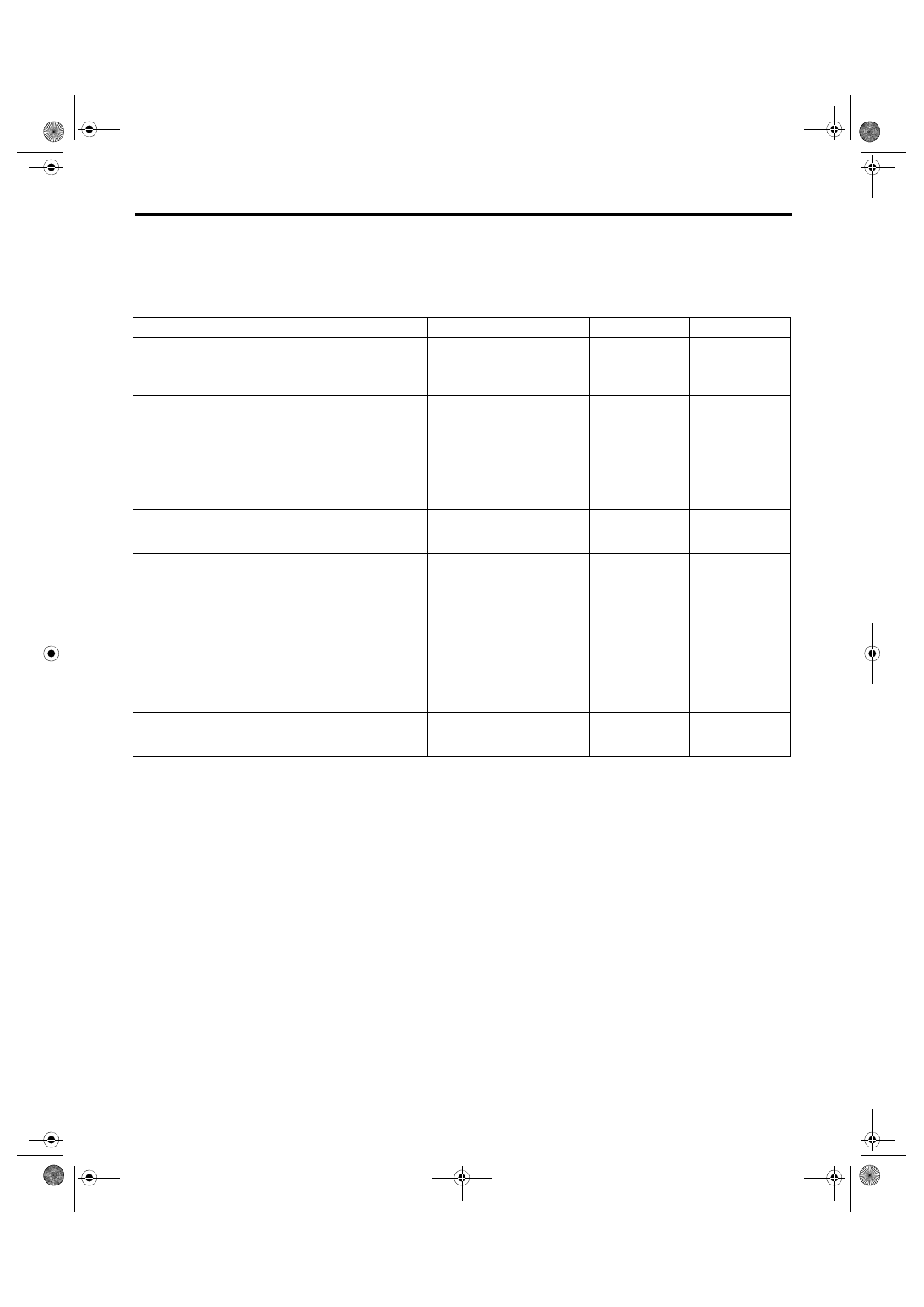
Step
Check
Yes
No
1
CHECK DTC.
Does the DTC related to G sen-
sor or yaw rate sensor appear
in the VDC diagnostics test
mode?
Perform the diag-
nosis according to
DTC.
2
CHECK IGNITION POWER SUPPLY CIRCUIT
OF DCCD CONTROL MODULE.
1) Connect the Subaru Select Monitor to the
vehicle.
2) Turn the ignition switch to ON.
3) Read the data of «Battery voltage» using
Subaru Select Monitor.
Is the voltage 11 V or more?
Repair the open
circuit of harness
between fuse (F/B
No. 12) and DCCD
control module, or
between fuse (F/B
No. 12) and bat-
tery.
3
CHECK DTC.
Is DTC P1720 displayed?
Perform the diag-
nosis according to
DTC.
4
CHECK DCCD CONTROL MODULE.
1) Drive the vehicle on a flat road.
2) Stop the vehicle with the front wheels in a
straight forward direction.
3) Read the data of «Yaw Rate» and «Lateral
G» using the Subaru Select Monitor.
Does the yaw rate and lateral G
value change according to the
vehicle behavior? When the
vehicle stops, is the yaw rate
value within –4 — 4 deg/s, and
also is the lateral G value within
–1.5 — 1.5 m/s
2
?
5
CHECK DTC.
1) Clear the memory.
2) Start the engine.
3) Read the DTC.
Is DTC P1769 displayed?
Replace the yaw
rate & G sensor.
6
CHECK OTHER DTC.
Is a DTC other than DTC P1769
displayed?
Perform the diag-
nosis according to
DTC.
Yaw rate & G sen-
sors are currently
normal.