Subaru Impreza 3 / Impreza WRX / Impreza WRX STI. Manual - part 445
 

  Index      Subaru     Subaru Impreza 3 / Impreza WRX / Impreza WRX STI - service repair manual 2008-2014 year


Search            


Content   ..  443  444  445  446   ..


Subaru Impreza 3 / Impreza WRX / Impreza WRX STI. Manual - part 445


6MT-117

Shifter Fork and Rod

MANUAL TRANSMISSION AND DIFFERENTIAL

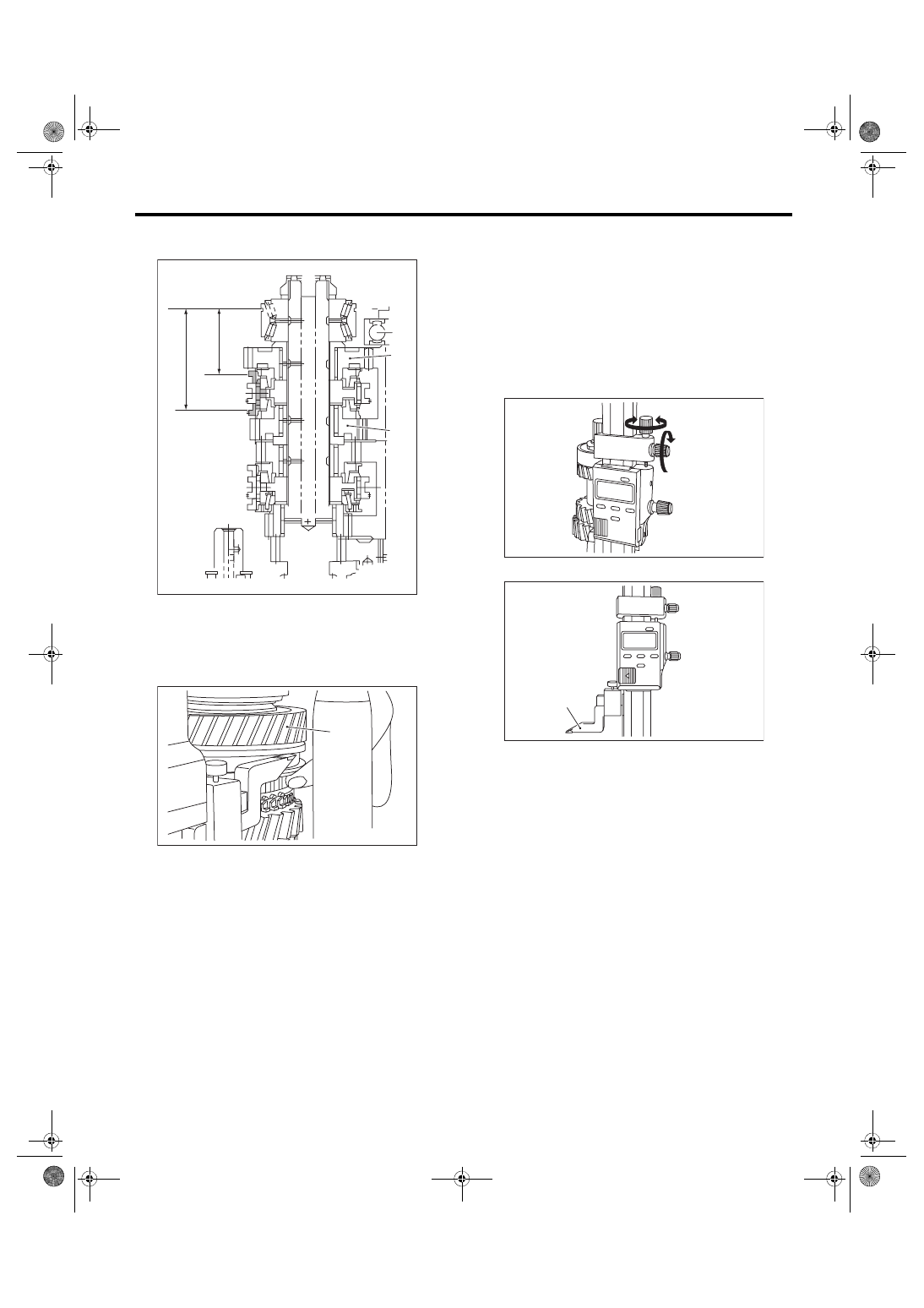
3) Use a height gauge to measure “D1” and “D2” as

shown in the figure.

(1) Shift up the 5th-6th sleeve all the way to the

6th drive gear side, and measure “D2”.

NOTE:

• Set the height gauge indicator near the measure-

ment target, and lock dial (1) as shown in the figure.

Turn dial (2), and set the indicator to the 6th side

end surface of the sleeve.

• The  measurement  is  to  be  performed  with  two

persons, while holding the sleeve straight.

• Turn approximately 72° at a time, and measure

the sleeve in 5 locations. Round down the 2 highest

and 2 lowest measurement values. The remaining

center value is used as the measurement value.

(2) Set the height gauge indicator upside down.

(A) 5th drive gear
(B) 6th drive gear

(A) 6th drive gear

MT-00712

D1

D2

(A)

(B)

MT-00713

(A)

(A) Indicator

MT-00585

(2)

(1)

MT-00710

(A)

6MT-118

Shifter Fork and Rod

MANUAL TRANSMISSION AND DIFFERENTIAL

(3) Shift down the 5th-6th sleeve all the way to

the 5th drive gear side, and measure “D1”.

NOTE:

• Set the height gauge indicator near the measure-

ment target, and lock dial (1) as shown in the figure.

Turn dial (2), and set the indicator to the 5th side

end surface of the sleeve.

• Turn approximately 72° at a time, and measure

the sleeve in 5 locations. Round down the 2 highest

and 2 lowest measurement values. The remaining

center value is used as the measurement value.

4) According to both of the measurements, calcu-

late the neutral position of the 5th-6th sleeve. From

the  following  calculation,  select  a  fork  rod  which

matches the calculated value.

Calculation: T = (D1 + D2) / 2

T: 5th-6th sleeve center position

D1:  Measured  length  from  the  shaft  rear  bearing

snap ring groove to the sleeve groove end, when

shifted to 5th gear [Value: +55 mm (2.17 in)]

D2: Measured length from the main shaft rear bear-

ing  snap  ring  groove  to  the  sleeve  groove  end,

when shifted to 6th gear
NOTE:

Attach the indicator upside down in comparison to

the setting procedures for the zero point. Add “d1”

[Value: 55 mm (2.17 in)] from the figure below to

“D1”, and measure “D1”.

(A) 5th drive gear

MT-00714

(A)

MT-00585

(2)

(1)

T mm (in)

Lot No. (marking)

M.SFT
Snap ring
805072010
[t = 1.65 mm 
(0.065 in)]

M.SFT
Snap ring
805072011
[t = 1.95 mm 
(0.077 in)]

M.SFT
Snap ring
805072012
[t = 2.25 mm 
(0.089 in)]

64.12 — 

64.42

(2.5244 — 

2.5362)

32945AA021 

(none)

32945AA031 

(2)

32945AA041 

(4)

64.42 — 

64.72

(2.5362 — 

2.5480)

32945AA011 

(1)

32945AA021 

(none)

32945AA031 

(2)

64.72 — 

65.02

(2.5480 — 

2.5598)

32945AA001 

(3)

32945AA011 

(1)

32945AA021 

(none)

T = Thickness

MT-00705

d1

6MT-119

Shifter Fork and Rod

MANUAL TRANSMISSION AND DIFFERENTIAL

4. REVERSE FORK ROD SELECTION

NOTE:

In the following conditions, perform the procedures

below.

• Reverse idler gear replacement.

• Reverse idler gear No. 2 replacement.

• Adapter plate replacement.

• Base replacement.

1) Insert  the  reverse  idler  gear  assembly  into  the

adapter plate.

2) Tighten the base COMPL attachment bolts.
Tightening torque:

25 N·m (2.5 kgf-m, 18.4 ft-lb)

3) Set the height gauge to the adapter plate. Lower

the height gauge indicator to the mating surface of

the adapter plate and case, and set to zero points.

ST 18853AA000 HEIGHT GAUGE

NOTE:

• The adapter plate will be the base point for the

measurement. Use a scraper to remove any gasket

material remaining on the end face.

• During  measurement,  do  not  place  the  height

gauge in the shaded area shown in the figure.

4) Shift the reverse sleeve to the reverse idler gear

No. 2, and measure “T”.

NOTE:

• Set the height gauge indicator near the measure-

ment target, and lock dial (1) as shown in the figure.

Turn dial (2), and set the indicator to the end face of

the reverse sleeve side.

• Turn approximately 72° at a time, and measure

the sleeve in 5 locations. Round down the 2 highest

and 2 lowest measurement values. The remaining

center value is used as the measurement value.

MT-00546

MT-00582

ST

MT-00583

(A) Reverse idler gear No. 2

(A) Reverse idler gear No. 2

MT-00715

(A)

T

MT-00716

(A)

MT-00585

(2)

(1)

6MT-120

Shifter Fork and Rod

MANUAL TRANSMISSION AND DIFFERENTIAL

5) Calculate  the  neutral  position  of  the  reverse

sleeve  according  to  the  measurement.  From  the

following calculation, select a fork rod which match-

es the calculated value.

Calculation: T + 4.8 mm (0.189 in)

T + 4.8 mm (0.189 in) mm 

(in)

Lot No. (marking)

33.50 — 33.80

(1.3189 — 1.3307)

32816AA110 (1)

33.80 — 34.10

(1.3307 — 1.3425)

32816AA130 (none)

34.10 — 34.40

(1.3425 — 1.3543)

32816AA140 (2)

T = Thickness


Content   ..  443  444  445  446   ..