Subaru Impreza 3 / Impreza WRX / Impreza WRX STI. Manual - part 440


  Index      Subaru     Subaru Impreza 3 / Impreza WRX / Impreza WRX STI - service repair manual 2008-2014 year


Search            


Content   ..  438  439  440  441   ..


Subaru Impreza 3 / Impreza WRX / Impreza WRX STI. Manual - part 440


6MT-97

Drive Pinion Shaft Assembly

MANUAL TRANSMISSION AND DIFFERENTIAL

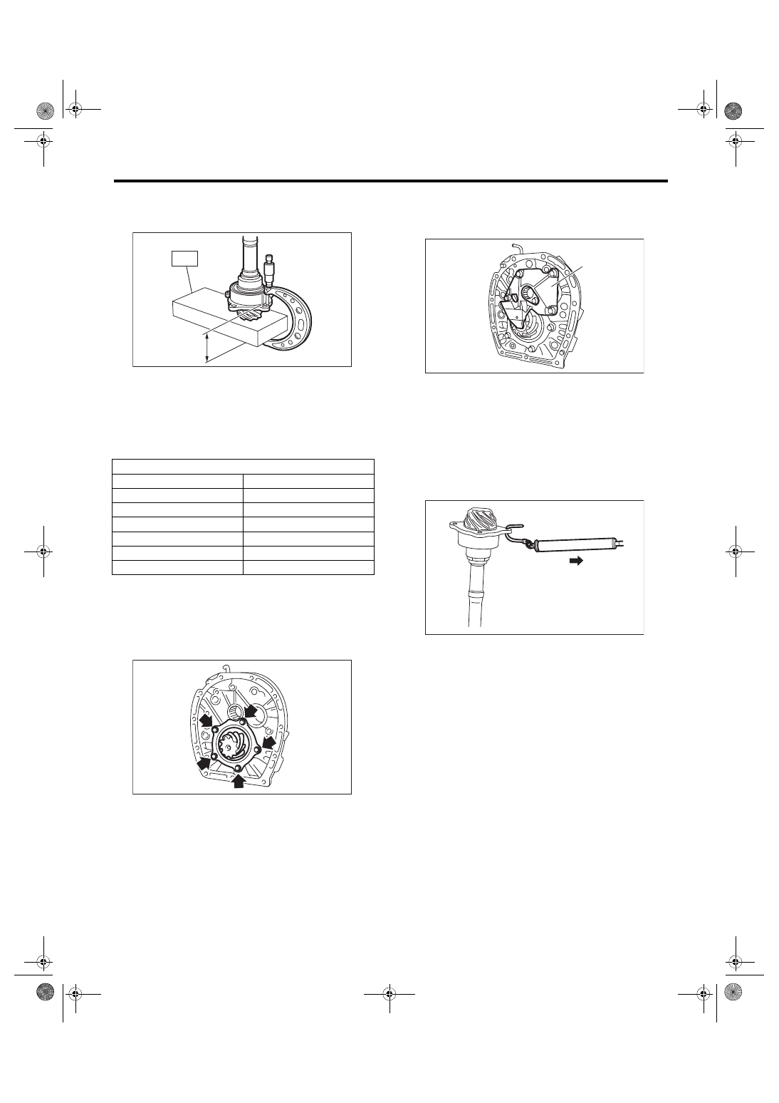
8) Using  the  ST,  measure  drive  pinion  measure-

ment B.

ST 398643600

GAUGE

9) Calculate from the calculation below to select 1

or 2 drive pinion shims from the following table.

6.5±0.0625 mm – (B – A) [0.26±0.0025 in – (B – A)]
NOTE:

A: Measurement value in step 1)

B: Measurement value in step 8)

10) Apply transmission gear oil to the side face of

the taper roller bearing, and attach the drive pinion

shaft and the selected shims to the adapter plate.
Tightening torque:

54 N·m (5.5 kgf-m, 39.8 ft-lb)

11) Install the oil guide A.
Tightening torque:

18 N·m (1.8 kgf-m, 13.3 ft-lb)

E: INSPECTION

1) Using  a  spring  scale,  measure  the  starting

torque. If the starting torque is outside the specifi-

cation range, replace the taper roller bearing.
Starting torque:

0 — 0.95 N (0 — 0.097 kgf, 0 — 0.21 lbf)

2) Gear

Replace gears in the following cases.

• The gear teeth surface is damaged or excessive-

ly worn.

3) Bearing

Replace the bearings in the following cases.

• Wear, rusting or damage of the bearings

• The bearing does not rotate smoothly or an ab-

normal noise is emitted when turning.

4) Adapter plate

Replace the adapter plate in the following cases:

• Wear, rusting or damage of the bearings

• Damage of the adapter plate

5) Check that the pipes and pipe chambers are not

damaged or clogged. Repair or replace if damaged

or clogged.

Drive pinion shim

Part No.

Thickness mm (in)

32295AA270

0.15 (0.0059)

32295AA280

0.175 (0.0069)

32295AA290

0.20 (0.0079)

32295AA300

0.225 (0.0089)

32295AA310

0.25 (0.0098)

32295AA320

0.275 (0.0108)

MT-00650

B

ST

MT-00642

(A) Oil guide A

MT-01624

(A)

MT-00651

6MT-98

Drive Pinion Shaft Assembly

MANUAL TRANSMISSION AND DIFFERENTIAL

F: ADJUSTMENT

1) Inspect  and  adjust  the  hypoid  driven  gear-to-

drive pinion backlash. <Ref. to 6MT-105, HYPOID

GEAR  BACKLASH,  ADJUSTMENT,  Front  Differ-

ential Assembly.>

2) Apply a thin uniform coat of lead-free red dye on

the surfaces of 3 or 4 hypoid driven gear teeth.

3) Install  the  drive  pinion  shaft  assembly  to  the

clutch housing, and tighten at least 4 bolts.
NOTE:

Install with the remaining liquid gasket, so that the

clutch  housing  and  the  adapter  plate  will  not  be

damaged.
Tightening torque:

50 N·m (5.1 kgf-m, 36.9 ft-lb)

4) Turn a few times using the ST.

ST 18631AA000 HANDLE

5) Remove the drive pinion shaft assembly, and in-

spect the mating condition of the teeth. If the tooth

contact is not correct, adjust the backlash or shim

thickness.

• Correct tooth contact

Check  item:  Tooth  contact  surface  is  slightly

shifted toward the toe side under a no-load con-

dition. (When driving, it moves towards the heel

side.)

• Face contact

Check item: Backlash is too large.

Contact pattern

Corrective action: Tighten the side retainer to move

the driven gear closer to the drive pinion shaft.

MT-00652

MT-00653

ST

(A) Toe side
(B) Heel side

(A)

(B)

MT-01401

AT-00208

AT-01253

6MT-99

Drive Pinion Shaft Assembly

MANUAL TRANSMISSION AND DIFFERENTIAL

• Flank contact

Check item: Backlash is too small.

Contact pattern

Corrective action: Loosen the side retainer to move

the driven gear away from the drive pinion shaft.

• Toe contact (inside contact)

Check item: Teeth contact area is too small.

Contact pattern

Adjustment: Reduce the thickness of the drive pin-

ion shim according to the procedure for moving the

drive pinion away from the driven gear.

• Heel contact (outside end contact)

Check item: Teeth contact area is too small.

Contact pattern

Adjustment: Increase thickness of the drive pinion

shim  according  to  the  procedures  for  moving  the

drive pinion closer to the driven gear.

AT-00209

AT-01254

AT-00210

AT-00213

AT-00211

AT-00212

6MT-100

Front Differential Assembly

MANUAL TRANSMISSION AND DIFFERENTIAL

21.Front Differential Assembly

A: REMOVAL

1) Remove  the  manual  transmission  assembly.

<Ref.  to  6MT-31,  REMOVAL,  Manual  Transmis-

sion Assembly.>

2) Prepare the transmission for overhaul. <Ref. to

6MT-37, Preparation for Overhaul.>

3) Remove  the  neutral  position  switch,  back-up

light  switch  and  harness.  <Ref.  to  6MT-41,  RE-

MOVAL, Neutral  Position Switch.>  <Ref.  to  6MT-

39, REMOVAL, Back-up Light Switch.>

4) Remove  the  extension  case.  <Ref.  to  6MT-43,

REMOVAL, Extension Case.>

5) Remove the transfer driven gear. <Ref. to 6MT-

55, REMOVAL, Transfer Driven Gear.>

6) Remove the center differential. <Ref. to 6MT-57,

REMOVAL, Center Differential.>

7) Remove  the  transmission  case.  <Ref.  to  6MT-

58, REMOVAL, Transmission Case.>

8) Remove the individual gear assemblies. <Ref. to

6MT-65, REMOVAL, Main Shaft Assembly.>

9) Remove the drive pinion shaft assembly. <Ref.

to 6MT-94, REMOVAL, Drive Pinion Shaft Assem-

bly.>

10) Remove the lock plates on both sides.

11) Remove the differential side retainers on both

sides using the ST.

ST1 18630AA010

WRENCH COMPL RETAIN-

ER (RH SIDE)

ST2 18630AA000

WRENCH ASSY (LH SIDE)

NOTE:

Be  careful  not  to  damage  the  section  where  the

clutch case retainer will be attached.

12) Remove the front differential.

B: INSTALLATION

1) Install  the  differential  assembly  to  the  clutch

housing.

2) Apply oil to the screw threads of the side retain-

er.

3) Remove the O-rings on both sides of the side re-

tainer.

(A) Lock plate

MT-01022

(A)

(A) LH side
(B) RH side

(A)

(B)

MT-00657

ST1

ST2


Content   ..  438  439  440  441   ..