Subaru Impreza 3 / Impreza WRX / Impreza WRX STI. Manual - part 439
6MT-93
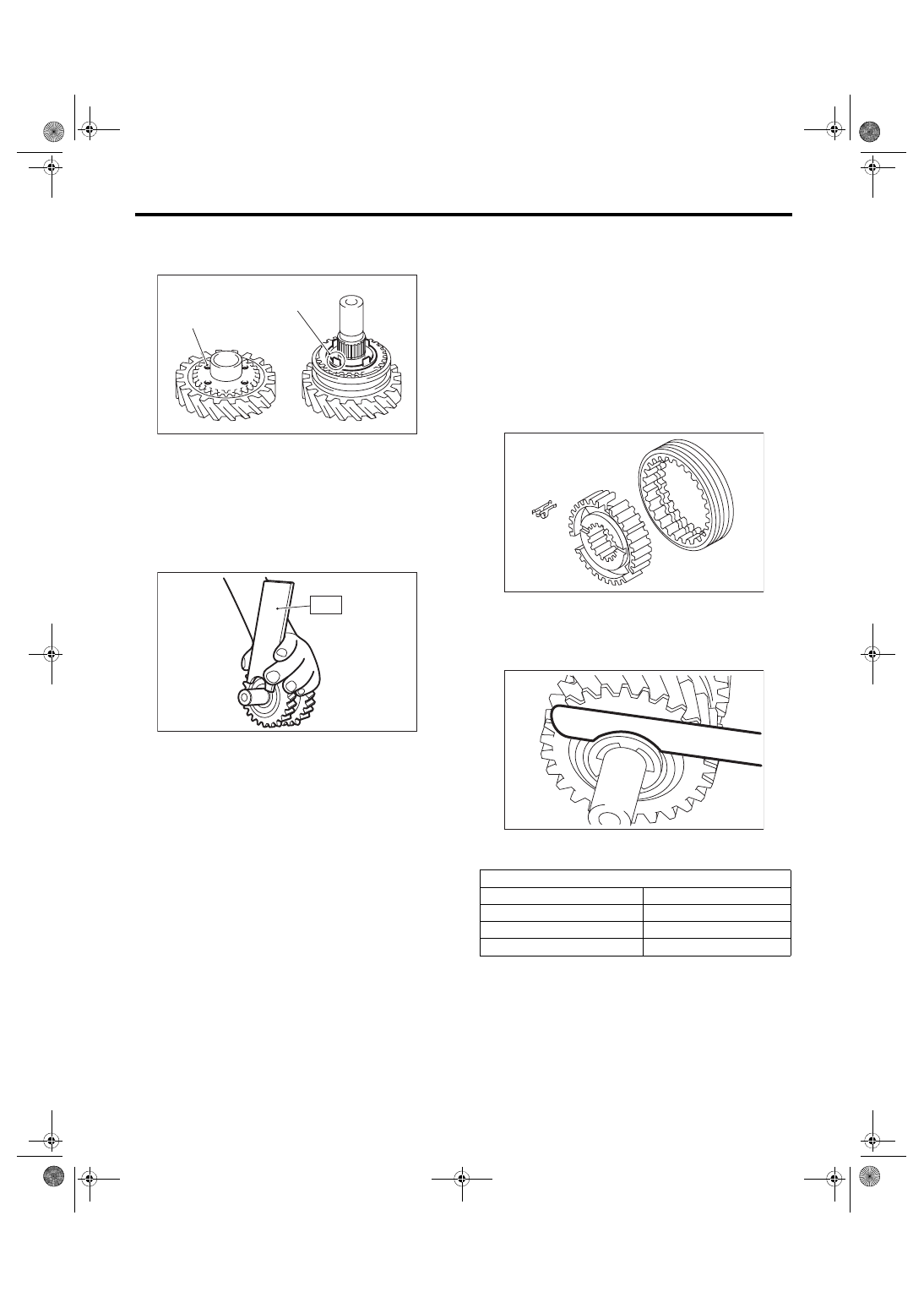
Reverse Idler Gear Assembly
MANUAL TRANSMISSION AND DIFFERENTIAL
12) Match the protrusion of the reverse synchro
cone to the hole on the reverse idler gear, and in-
stall the reverse idler gear.
13) Point the groove towards the reverse idler gear,
and attach the counter high & low washer and the
washer.
14) Using the ST, install the snap ring.
ST 18672AA000 GUIDE CLIP
15) Inspect and adjust the clearance between the
snap ring and the washer. <Ref. to 6MT-93, IN-
SPECTION, Reverse Idler Gear Assembly.>
16) Install a new straight pin.
E: INSPECTION
Disassembled parts should be washed with clean-
ing solvent first, then inspected carefully.
1) Bearing
Replace the bearings in the following cases.
• Wear, rusting or damage of the bearings
• The bearing does not rotate smoothly or an ab-
normal noise is emitted when turning.
• The bearing has other defects.
2) Bushing (each gear)
Replace the bushing in following cases.
• The sliding surface is damaged or abnormally
worn.
3) Gear
Replace gears in the following cases.
• The gear teeth surface is damaged or excessive-
ly worn.
• The contact area of the baulk ring is damaged.
• The inner face of the gear is worn.
4) Baulk ring, synchro cone
Replace the baulk ring and synchro cone in the fol-
lowing cases.
• Wear, rusting or damage of the baulk ring
5) Shifting insert key
Replace the shifting insert key if deformed, exces-
sively worn or defective in any way.
6) Check clearance between the snap ring and
washer.
Clearance specification:
0.1 — 0.3 mm (0.0039 — 0.0118 in)
If the clearance is out of the specification, select a
snap ring from the following table and replace it.
After replacing the snap ring, inspect the clearance.
(A) Protrusion on the reverse synchro cone
(B) Hole of the reverse idler gear
MT-01508
(A)
(B)
MT-00638
ST
Snap ring
Part No.
Thickness mm (in)
031319000
1.50 (0.059)
805019030
1.60 (0.062)
805019010
1.72 (0.068)
MT-00581
MT-00639