Subaru Impreza 3 / Impreza WRX / Impreza WRX STI. Manual - part 428


  Index      Subaru     Subaru Impreza 3 / Impreza WRX / Impreza WRX STI - service repair manual 2008-2014 year


Search            


Content   ..  426  427  428  429   ..


Subaru Impreza 3 / Impreza WRX / Impreza WRX STI. Manual - part 428


6MT-49

Extension Case

MANUAL TRANSMISSION AND DIFFERENTIAL

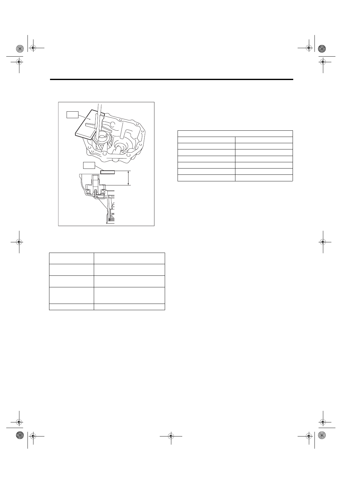
2) Measure depth “Y” between the end of the ST

and the transfer drive gear.

ST 398643600

GAUGE

3) Using  the  following  calculation,  calculate  the

transfer drive gear adjusting washer value “t”.

t = {Y – 15 mm (0.59 in)} – {Z – 15 mm (0.59 in)} –

0.75 — 0.95 mm (0.030 — 0.037 in)

4) Refer  to  the  calculated  value  “t”  to  select  the

closest adjusting washer from the following table.
Standard clearance between the adjusting 

washer and transfer drive gear

0.75 — 0.95 mm (0.030 — 0.037 in)

NOTE:

Match to be within the standard clearance range.

5) Install the selected adjusting washer.

t

mm (in)

Transfer drive gear adjusting washer 
thickness

Y

mm (in)

Depth between the end of the ST 
and the transfer drive gear

Z

mm (in)

Height from the end of the transmis-
sion case to the end of the ST.

0.75 — 0.95 mm

(0.030 — 0.037 in)

Standard clearance between the 
adjusting washer and transfer drive 
gear

15 mm (0.591 in)

Thickness of ST

MT-01421

ST

ST

Y

Adjusting washer (36.3 × 52 × t)

Part No.

Thickness mm (in)

803036070

0.80 (0.0315)

803036071

0.95 (0.0374)

803036072

1.10 (0.0433)

803036073

1.25 (0.0492)

803036074

1.40 (0.0551)

803036075

0.65 (0.0256)

6MT-50

Reverse Check System

MANUAL TRANSMISSION AND DIFFERENTIAL

12.Reverse Check System

A: REMOVAL

1) Remove  the  manual  transmission  assembly

from  the  vehicle.  <Ref.  to  6MT-31,  REMOVAL,

Manual Transmission Assembly.>

2) Prepare the transmission for overhaul. <Ref. to

6MT-37, Preparation for Overhaul.>

3) Remove  the  extension  case.  <Ref.  to  6MT-43,

REMOVAL, Extension Case.>

4) Remove the snap ring and washer from the re-

verse check shaft.

5) Remove the reverse check shaft and spring from

the extension case.

6) Remove  the  straight  pin,  and  remove  the  re-

verse  check  lever  and  oil  seal  from  the  reverse

check shaft.

7) Remove the plug from the extension case, and

remove the gasket, spring and plunger.

8) Remove the reverse lock plunger.

(A) Snap ring
(B) Washer

MT-00494

(A)

(B)

MT-00495

(A) Straight pin
(B) Reverse check lever

(C) Oil seal

(A) Plug
(B) Gasket

(C) Spring
(D) Plunger

(A) Reverse lock plunger

MT-00496

(A)

(C)

(B)

MT-01818

(A)

(B)

(C)

(D)

MT-00498

(A)

6MT-51

Reverse Check System

MANUAL TRANSMISSION AND DIFFERENTIAL

B: INSTALLATION

1) Insert the reverse lock plunger.

2) Install  the  reverse  check  plug,  spring,  gasket,

and plug in order.
NOTE:

Use a new gasket.
Tightening torque:

41 N·m (4.2 kgf-m, 30.2 ft-lb)

3) Install the spring and reverse check shaft to the

extension case.
NOTE:

Confirm that the end of the spring matches the hole

of the reverse check shaft and the cut out of the ex-

tension case.

4) Install the washer and snap ring.

(A) Plug
(B) Gasket

(C) Spring
(D) Reverse check plug

MT-01818

(A)

(B)

(C)

(D)

(A) Reverse check shaft
(B) Spring

(C) Hole
(D) Cut out

(A) Snap ring
(B) Washer

(A)

(A)

(C)

(D)

(B)

(B)

MT-00499

MT-00494

(A)

(B)

6MT-52

Reverse Check System

MANUAL TRANSMISSION AND DIFFERENTIAL

5) Attach ST1 to the reverse check shaft. Install the

new oil seal, and push it in using ST2.

ST1 18671AA000

OIL SEAL GUIDE

ST2 18657AA010

INSTALLER

6) Insert the reverse check lever, and turn the re-

verse check shaft until the plunger is first pushed

in.

7) Match the hole of the reverse check lever and

the reverse check shaft, and attach the straight pin.
NOTE:

Use a new straight pin.

8) Check that the reverse check is operating cor-

rectly.  <Ref.  to  6MT-52,  INSPECTION,  Reverse

Check System.>

9) Install the extension case. <Ref. to 6MT-43, IN-

STALLATION, Extension Case.>

10) Install the manual transmission assembly to the

vehicle. <Ref. to 6MT-33, INSTALLATION, Manual

Transmission Assembly.>

C: INSPECTION

1) Check that there is no damage on any parts.

2) Check that the reverse check lever is operating

smoothly.

3) Inspect that there is no oil leak at the oil seal sec-

tion of the reverse check shaft. If there is oil leak-

age, replace the oil seal.

4) Check the operation of the reverse check.

(1) When the reverse check lever is in the fol-

lowing position, the plunger is pressed, or the

gear can shift into reverse.

(2) When the reverse check lever is in the fol-

lowing position, the plunger is not pressed, or

the gear cannot shift into reverse.

5) If it is not as specified, reassemble the reverse

check system.

(A) Oil seal

(A) Plunger
(B) Reverse check shaft

(A) Reverse check shaft
(B) Reverse check lever

(C) Hole

MT-00500

(A)

ST2

ST1

MT-00501

(A)

(B)

MT-00502

(A)

(B)

(C)

MT-00503

MT-00504


Content   ..  426  427  428  429   ..