Subaru Impreza 3 / Impreza WRX / Impreza WRX STI. Manual - part 427


  Index      Subaru     Subaru Impreza 3 / Impreza WRX / Impreza WRX STI - service repair manual 2008-2014 year


Search            


Content   ..  425  426  427  428   ..


Subaru Impreza 3 / Impreza WRX / Impreza WRX STI. Manual - part 427


6MT-45

Extension Case

MANUAL TRANSMISSION AND DIFFERENTIAL

5) Select the thrust washer of the bearing, and at-

tach to the extension case. <Ref. to 6MT-45, AD-

JUSTMENT, Extension Case.>

6) Apply a thin coat of oil to the outer surface of the

bearing cone, and attach to the extension case.

7) Install the shift bracket.
Tightening torque:

25 N·m (2.5 kgf-m, 18.4 ft-lb)

8) Attach the oil guide and the transfer driven gear.

<Ref. to 6MT-53, INSTALLATION, Transfer Drive

Gear.>

E: INSPECTION

1) Check  to  make  sure  there  is  no  damage  or

cracks on the extension case. If damage or crack-

ing is found, replace the extension case.

2) Inspect  for  oil  leaks  at  the  extension  case  and

transmission case oil seals and mating surfaces. If

there are oil leaks, replace the oil seal and liquid

gasket.

F: ADJUSTMENT

1. TRANSFER DRIVEN GEAR BEARING 

THRUST WASHER ADJUSTMENT

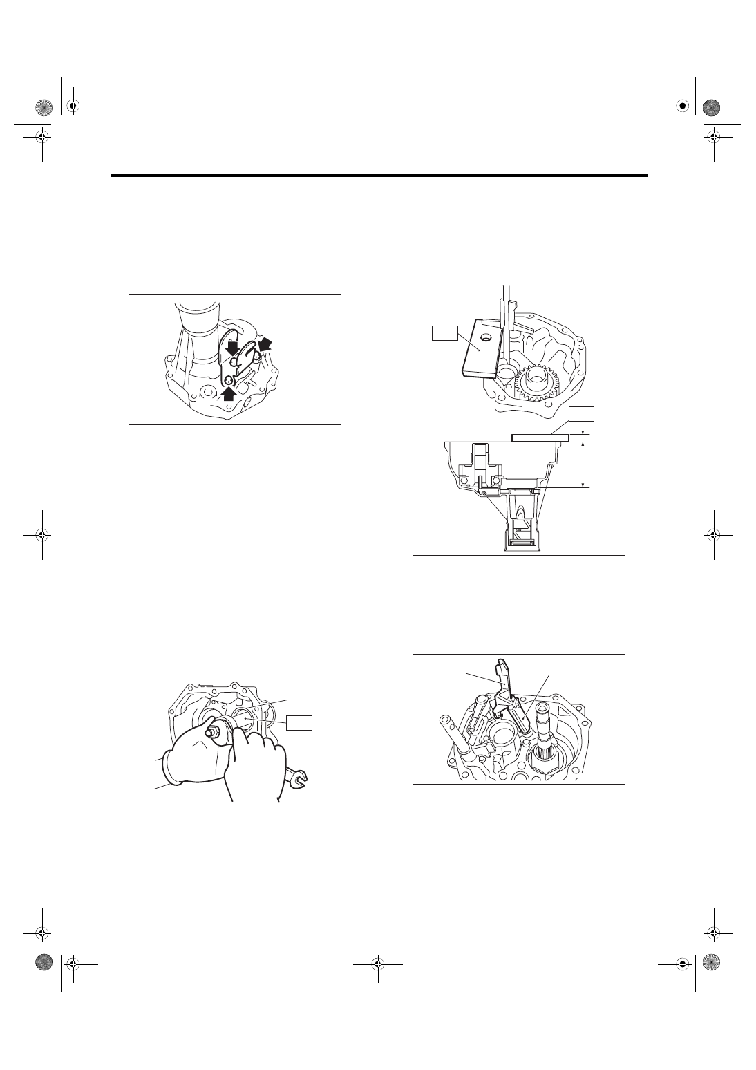
1) Remove  the  bearing  cone  from  the  extension

case using the ST.

ST 18758AA000 PULLER

2) Remove the adjusting washer.

3) Measure depth “Z” between the extension case

end area and bearing cone contact area.

ST 398643600

GAUGE

NOTE:

When measuring depth “Z”, subtract the thickness

of the ST [15 mm (0.59 in)] from the measured val-

ue.

4) Remove the transfer driven gear. <Ref. to 6MT-

55, REMOVAL, Transfer Driven Gear.>

5) Remove the center differential. <Ref. to 6MT-57,

REMOVAL, Center Differential.>

6) Remove the oil guides G and H.

(A) Bearing cone

MT-00478

MT-00479

(A)

ST

(A) 15 mm (0.59 in)

(A) Oil guide G
(B) Oil guide H

MT-01420

(A)

Z

ST

ST

MT-01728

(A)

(B)

6MT-46

Extension Case

MANUAL TRANSMISSION AND DIFFERENTIAL

7) Remove the snap ring and flat washer from the

selector arm area.

8) Using an ST, remove the neutral set spring and

support.

ST1 18756AA000

CLAW

ST2 399893600

PLIER

9) Lift the striking rod, and remove the straight pin.

10) Remove the selector arm No. 2, shifter arm, se-

lector plunger and spring.

11) Attach the bearing cone to the transfer driven

gear.

12) Set the ST.

ST 18831AA000 GAUGE

13) Turn the transfer driven gear 10 or more times

to seat the bearing properly.

(A) Snap ring
(B) Flat washer

(A) Striking rod
(B) Straight pin

MT-01616

(B)

(A)

MT-01092

ST2

ST1

MT-01307

(A)

(B)

(A) Selector arm No. 2
(B) Shifter arm

(C) Selector plunger

MT-02713

(B)

(A)

(C)

MT-00489

ST

6MT-47

Extension Case

MANUAL TRANSMISSION AND DIFFERENTIAL

14) Measure depth “Y” between the end of the ST

and the bearing cone.

ST 18831AA000 GAUGE

15) Using  the  following  calculation,  calculate  the

transfer driven gear bearing adjusting washer value

“t”.

t = Z – (100 – Y) – {0.02 — 0.11 mm (0.0008 —

0.0043 in)}

16) Refer  to  the  calculated  value  “t”  to  select  the

closest thrust washer from the following table.
Standard clearance between the adjusting 

washer and taper roller bearing

0.02 — 0.11 mm (0.0008 — 0.0043 in)

NOTE:

Match to be within the standard clearance range.

t

mm (in)

Transfer driven gear bearing adjust-
ing washer thickness

Y

mm (in)

Depth between the end of the ST 
and the bearing cone

Z

mm (in)

Depth between the end of the 
extension case and the bearing 
cone contact area

0.02 — 0.11 mm

(0.0008 — 0.0043 in)

Standard clearance between the 
adjusting washer and taper roller 
bearing

100 mm
(3.94 in)

Height of ST

MT-00490

Y

ST

Adjusting washer (50 × 61 × t)

Part No.

Thickness t mm (in)

803050060

0.50 (0.0197)

803050061

0.55 (0.0217)

803050062

0.60 (0.0236)

803050063

0.65 (0.0256)

803050064

0.70 (0.0276)

803050065

0.75 (0.0295)

803050066

0.80 (0.0315)

803050067

0.85 (0.0335)

803050068

0.90 (0.0354)

803050069

0.95 (0.0374)

803050070

1.00 (0.0394)

803050071

1.05 (0.0413)

803050072

1.10 (0.0433)

803050073

1.15 (0.0453)

803050074

1.20 (0.0472)

803050075

1.25 (0.0492)

803050076

1.30 (0.0512)

803050077

1.35 (0.0531)

803050078

1.40 (0.0551)

803050079

1.45 (0.0570)

6MT-48

Extension Case

MANUAL TRANSMISSION AND DIFFERENTIAL

17) Install the selector arm No. 2, shifter arm, se-

lector plunger and spring.

18) Install a new straight pin.

19) Using the ST, install the neutral set spring and

support.

ST1 18756AA000

CLAW

ST2 399893600

PLIER

20) Install the flat washer and snap ring to the se-

lector arm area.

21) Install the center differential. <Ref. to 6MT-57,

INSTALLATION, Center Differential.>

2. TRANSFER DRIVE GEAR THRUST 

WASHER SELECTION

1) Measure  height  “Z”  between  the  transmission

case end area and ST.

ST 398643600

GAUGE

(A) Selector arm No. 2
(B) Shifter arm

(C) Selector plunger

MT-02713

(B)

(A)

(C)

MT-01092

ST2

ST1

(A) Snap ring
(B) Flat washer

MT-01616

(B)

(A)

Z

ST

MT-00949


Content   ..  425  426  427  428   ..