Subaru Impreza 3 / Impreza WRX / Impreza WRX STI. Manual - part 394


  Index      Subaru     Subaru Impreza 3 / Impreza WRX / Impreza WRX STI - service repair manual 2008-2014 year


Search            


Content   ..  392  393  394  395   ..


Subaru Impreza 3 / Impreza WRX / Impreza WRX STI. Manual - part 394


CS-27

Reverse Check Cable

CONTROL SYSTEMS

D: ADJUSTMENT

1) Lift up the vehicle.

2) Remove the transmission under cover.

3) Remove  the  center  exhaust  pipe.  <Ref.  to

EX(STI)-8, REMOVAL, Center Exhaust Pipe.>

4) Remove the heat shield cover.

5) Remove  the  crossmember.  <Ref.  to  6MT-29,

REMOVAL, Transmission Mounting System.>

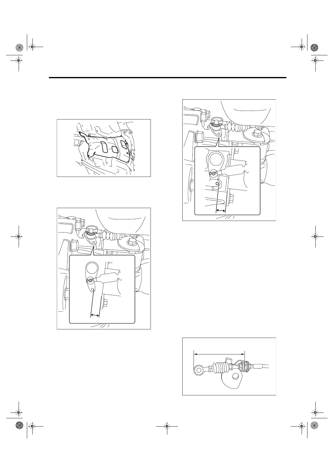
6) Measure the distance “A” from the shift bracket

seating face on transmission side to the hole edge

of the reverse check lever.

7) Measure the distance “B” from the shift bracket

seating face on transmission side to the hole edge

of the extension case.

8) Calculate  the  following  formula  and  determine

the amount of cable adjustment.

T mm = (A – B) × 0.56

[T in = (A – B) × 0.56]

T: Amount of cable adjustment

A: Distance from the shift bracket seating face on

transmission side to the hole edge of the reverse

check lever

B: Distance from the shift bracket seating face on

transmission side to the hole edge of the extension

case
NOTE:

• If the value “T” (amount of cable adjustment) is

positive (+), shorten the length “C” (from cable plate

edge to reverse check cable) by using adjustment

procedures.

• If the value “T” (amount of cable adjustment) is

negative  (–),  lengthen  the  length  “C”  (from  cable

plate edge to reverse check cable) by using adjust-

ment procedures.

MT-01660

A

CS-01748

B

CS-01749

(C)

CS-01757

CS-28

Reverse Check Cable

CONTROL SYSTEMS

9) Remove the snap pin and washer, and separate

the reverse check cable from the reverse check le-

ver.

10) Move the transmission to the right side, and re-

move the stay bolts and the reverse check cable.
NOTE:

If  the  transmission  is  not  moved  aside,  the  stay

bolts may contact the body and cause damage.

11) Check the adjustment of the reverse check ca-

ble.

(1) Add a marking on the reverse check cable.

(2) According to the value “T” (amount of cable

adjustment) calculated in the step 8), turn the

lock nut of reverse check cable back and forth,

then  adjust  the  length  “C”  (from  cable  plate

edge to reverse check cable).

NOTE:

• Turning the lock nut toward front of the vehicle

makes the cable length shorter and toward the rear

of the vehicle the cable length longer.

• The amount of the cable adjustment by one lock

nut rotation is 1 mm (0.04 in).

• Turn the lock nuts on both sides by the same ad-

justment amount.

(3) Tighten the lock nut.

Tightening torque:

6 N·m (0.6 kgf-m, 4.4 ft-lb)

12) Move the transmission to the right side, and in-

stall the stay.
Tightening torque:

T: 32 N·m (3.3 kgf-m, 23.6 ft-lb)

(A) Snap pin
(B) Washer

(C) Reverse check cable

(A) Stay
(B) Stay bolt

(A) Marking

CS-00220

(B)

(A)

(C)

CS-00245

(A)

(B)

(A)

CS-01750

(A) Stay

(C)

CS-01757

CS-00246

(A)

T

CS-29

Reverse Check Cable

CONTROL SYSTEMS

13) Install  the  reverse  check  cable,  washer  and

snap pin to the reverse check lever.
NOTE:

Make sure to point the snap pin in an appropriate

direction.

14) Make sure the hole of extension case is aligned

with  that  of  reverse  check  lever.  If  the  hole  posi-

tions are not aligned, return to the step 6) and re-

peat  the  adjustment  procedures  of  the  reverse

check cable.
NOTE:

• Check that the M3 bolt goes through the hole of

reverse  check  lever  and  can  be  inserted  into  the

hole of extension case.

• When checking visually, confirm that the gap of

hole positions is 0.5 mm (0.02 in) or less.

NOTE:

If the hole positions are not aligned after repeating

the reverse check cable adjustment, adjust the ca-

ble hole position to the reference standard.
Distance from the shift bracket seating face on 

transmission side to the hole edge of the re-

verse check lever “A”:

Reference standard

16 mm (0.63 in)

15) Install the crossmember. <Ref. to 6MT-29, IN-

STALLATION, Transmission Mounting System.>

16) Install the heat shield cover.
Tightening torque:

18 N·m (1.8 kgf-m, 13.3 ft-lb)

17) Install  the  center  exhaust  pipe.  <Ref.  to

EX(STI)-9,  INSTALLATION,  Center  Exhaust

Pipe.>

18) Install the transmission under cover.
Tightening torque:

18 N·m (1.8 kgf-m, 13.3 ft-lb)

(A) Reverse check cable
(B) Washer

(C) Snap pin
(D) Front side

(A) Hole of reverse check lever
(B) Hole of extension case

CS-00224

(B)

(D)

(C)

(A)

(A)

(B)

CS-01751

A

CS-01752

MT-01660

CS-30

General Diagnostic Table

CONTROL SYSTEMS

4. General Diagnostic Table

A: INSPECTION

Symptoms

Possible cause

Corrective action

MT gear shift 
lever (6MT)

Cannot shift into reverse.

Adjust the reverse check cable.

Can shift into reverse when the slider is not pulled up. Adjust or replace the reverse check cable.
Slider cannot be pulled up or sticks in the pulled-up 
position.

• Check the reverse check system of the transmission.
• Adjust or replace the reverse check cable.


Content   ..  392  393  394  395   ..