Subaru Impreza 3 / Impreza WRX / Impreza WRX STI. Manual - part 347
GD(H4DOTC)-140
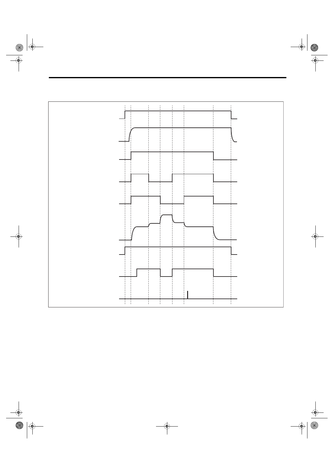
Diagnostic Trouble Code (DTC) Detecting Criteria
GENERAL DESCRIPTION
4. DIAGNOSTIC METHOD
Measure secondary air delivery pipe pressure, pulse of secondary air delivery pipe pressure and secondary
air pipe airflow amount.
(1)
IG
(6)
Secondary air delivery pipe pres-
sure (psi)
(10) Barometric pressure (Pas) mea-
surement before secondary air
control
(2)
Ne
(7)
Diagnosis enable condition
(11) Right bank all closed pressure
(P0R) measurement
(3)
Secondary air pump operating
status
(8)
Pump supply pressure check
(judgment)
(12) Both banks all closed pressure
(P0RL) measurement
(4)
E-COMB valve (right hand) status
(9)
Flow amount check (judgment)
(13) Left bank all closed pressure
(P0L) measurement
(5)
E-COMB valve (left hand) status
(2)
(7)
(8)
(6)
(12)
(11)
(10)
(13)
(9)
EN-05591
(3)
ON
OFF
(1)
ON
OFF
(4)
OPEN
CLOSE
(5)
OPEN
CLOSE