Subaru Impreza 3 / Impreza WRX / Impreza WRX STI. Manual - part 186
 

  Index      Subaru     Subaru Impreza 3 / Impreza WRX / Impreza WRX STI - service repair manual 2008-2014 year


Search            


Content   ..  184  185  186  187   ..


Subaru Impreza 3 / Impreza WRX / Impreza WRX STI. Manual - part 186


CO(w/o STI)-13

Engine Coolant

COOLING

3. Engine Coolant

A: INSPECTION

NOTE:

When adding the engine coolant, always use SUB-

ARU Super Coolant.

1) Park the vehicle on a level surface.

2) Check  the  engine  coolant  amount,  and  if  the

coolant level is low, check for the coolant leakage,

and then add the engine coolant.

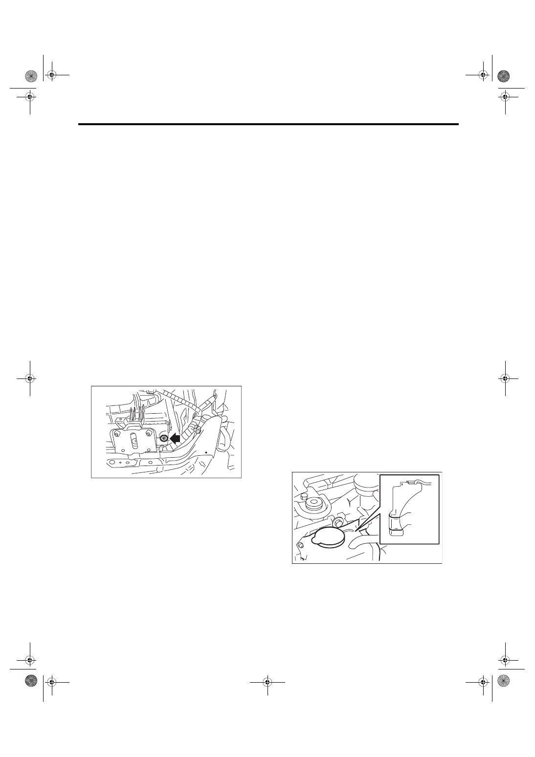
(1) Make  sure  the  engine  coolant  level  in  the

reservoir  tank  is  between  “FULL”  and  “LOW”

with the engine in a cold condition.

(2) Open  the  cap  of  coolant  filler  tank,  and

check that the engine coolant is filled up to the

filler neck position.

B: REPLACEMENT

1. DRAINING OF ENGINE COOLANT

1) Lift up the vehicle.

2) Remove  the  under  cover.  <Ref.  to  EI-28,  RE-

MOVAL, Front Under Cover.>

3) Remove the drain plug to drain engine coolant

into container.
NOTE:

Remove the coolant filler tank cap so that engine

coolant will drain faster.

4) Install the drain plug.
NOTE:

Use new O-rings.

5) Install the under cover. <Ref. to EI-28, INSTAL-

LATION, Front Under Cover.>

2. FILLING OF ENGINE COOLANT

1) Pour cooling system conditioner through the fill-

er neck of coolant filler tank.
Cooling system protective agent:

Refer to “SPECIFICATION” for cooling sys-

tem protective agent. <Ref. to CO(w/o STI)-2, 

SPECIFICATION, General Description.>

2) Fill the engine coolant into coolant filler tank up

to the filler neck position.
Recommended engine coolant:

Refer to “SPECIFICATION” for recommended 

engine coolant. <Ref. to CO(w/o STI)-2, 

SPECIFICATION, General Description.>

Engine coolant level:

Refer to “SPECIFICATION” for engine cool-

ant level. <Ref. to CO(w/o STI)-2, SPECIFICA-

TION, General Description.>

Engine coolant concentration:

Refer to “ADJUSTMENT” for the recommend-

ed engine coolant concentration. <Ref. to 

CO(w/o STI)-14, ADJUSTMENT, Engine Cool-

ant.>

CAUTION:

Do not confuse the cap of coolant filler tank and

cap of radiator.
NOTE:

• When  pouring  the  engine  coolant,  the  radiator

side cap must not be removed.

• The  SUBARU  Super  Coolant  contains  anti-

freeze and anti-rust agents, and is especially made

for  Subaru  engines  with  an  aluminum  cylinder

block.  Be  sure  to  use  SUBARU  Super  Coolant,

since other coolant may cause corrosion.

3) Fill engine coolant into the reservoir tank up to

“FULL” level.

CO-02501

CO-02764

FULL

LOW

CO(w/o STI)-14

Engine Coolant

COOLING

4) Close the coolant filler tank cap, and start the en-

gine. Race 5 to 6 times at 3,000 rpm or less, then

stop the engine. (Complete this operation within 40

seconds.)

5) Wait for one minute after the engine stops, then

open the coolant filler tank cap. If the engine cool-

ant level drops, add engine coolant into coolant fill-

er tank up to the filler neck position.

6) Perform the procedures 4) and 5) again.

7) Install  the  coolant  filler  tank  cap  and  reservoir

tank cap properly.

8) Start the engine and operate the heater at max-

imum hot position and the blower speed setting to

“LO”.

9) Run the engine at 3,000 rpm or less until radiator

fan starts and stops.
NOTE:

Be careful with the engine coolant temperature to

prevent overheating.

10) Stop the engine and wait until the engine cool-

ant temperature lowers to 30°C (86°F) or less.

11) Open the coolant filler tank cap. If the engine

coolant  level  drops,  add  engine  coolant  into  the

coolant filler tank up to the filler neck position and

the reservoir tank to “FULL” level.

12) Install the coolant filler tank cap and reservoir

tank cap properly.

13) Set the heater setting to maximum hot position

and the blower speed setting to “LO” and start the

engine. Perform racing at 3,000 rpm or less. If the

flowing sound is heard from the heater core, repeat

the procedures from step 9).

C: ADJUSTMENT

1. PROCEDURE TO ADJUST THE SUBARU SUPER COOLANT CONCENTRATION

CAUTION:

Use the SUBARU Super Coolant with a 50 — 60% concentration in order to obtain maximum anti-

freeze and anti-rust performance.

To adjust the concentration of SUBARU Super Coolant according to temperature, find the proper SUBARU

Super Coolant concentration in the table, and add dilution water to the SUBARU Super Coolant (concentrat-

ed type) until it reaches the proper dilution.

Engine coolant and diluting water:

Refer to “SPECIFICATION” for recommended engine coolant and diluting water. <Ref. to CO(w/o 

STI)-2, SPECIFICATION, General Description.>

Relationship of SUBARU Super Coolant concentration and freezing temperature

SUBARU Super Coolant concentration

50%

55%

60%

Freezing temperature

–36°C (–33°F)

–41°C (–42°F)

–50°C (–58°F)

CO(w/o STI)-15

Water Pump

COOLING

4. Water Pump

A: REMOVAL

1) Remove the radiator. <Ref. to CO(w/o STI)-19,

REMOVAL, Radiator.>

2) Remove  the  V-belts.  <Ref.  to  ME(w/o  STI)-38,

REMOVAL, V-belt.>

3) Remove the crank pulley. <Ref. to ME(w/o STI)-

45, REMOVAL, Crank Pulley.>

4) Remove the timing belt cover. <Ref. to ME(w/o

STI)-47, REMOVAL, Timing Belt Cover.>

5) Remove the timing belt. <Ref. to ME(w/o STI)-

48, REMOVAL, Timing Belt.>

6) Remove the automatic belt tension adjuster (A).

7) Remove the belt idler (B).

8) Remove the belt idler No. 2 (C).

9) Remove the cam sprocket LH. <Ref. to ME(w/o

STI)-57, REMOVAL, Cam Sprocket.>

10) Remove the belt cover No. 2 LH.

11) Remove the tensioner bracket.

12) Disconnect the hose from water pump.

13) Remove the water pump.

B: INSTALLATION

1) Install the water pump onto cylinder block LH.
NOTE:

• Use a new gasket.

• When installing the water pump, tighten the bolts

in two stages in alphabetical sequence as shown in

figure.
Tightening torque:

First:

12 N·m (1.2 kgf-m, 8.9 ft-lb)

Second:

12 N·m (1.2 kgf-m, 8.9 ft-lb)

2) Install the hose to water pump.

3) Install the tensioner bracket.
Tightening torque:

24.5 N·m (2.5 kgf-m, 18.1 ft-lb)

CO-02726

(A)

(B)

(C)

CO-02908

ME-04984

CO-00021

ME-04743

(F)

(C)

(A)

(E)

(D)

(B)

ME-04984

CO(w/o STI)-16

Water Pump

COOLING

4) Install the belt cover No. 2 LH.
Tightening torque:

5 N·m (0.5 kgf-m, 3.7 ft-lb)

5) Install  the  cam  sprocket  LH.  <Ref.  to  ME(w/o

STI)-57, INSTALLATION, Cam Sprocket.>

6) Install the belt idler No. 2 (C).
Tightening torque:

39 N·m (4.0 kgf-m, 28.8 ft-lb)

7) Install the belt idler (B).
Tightening torque:

25 N·m (2.5 kgf-m, 18.4 ft-lb)

8) Install  the  automatic  belt  tension  adjuster  (A)

with the tension rod held by a pin. <Ref. to ME(w/o

STI)-50,  AUTOMATIC  BELT  TENSION  ADJUST-

ER  ASSEMBLY  AND  BELT  IDLER,  INSTALLA-

TION, Timing Belt.>

9) Install the timing belt. <Ref. to ME(w/o STI)-51,

TIMING BELT, INSTALLATION, Timing Belt.>

10) Install  the  timing  belt  cover.  <Ref.  to  ME(w/o

STI)-47, INSTALLATION, Timing Belt Cover.>

11) Install the crank pulley. <Ref. to ME(w/o STI)-

45, INSTALLATION, Crank Pulley.>

12) Install the V-belts. <Ref. to ME(w/o STI)-38, IN-

STALLATION, V-belt.>

13) Install  the  radiator.  <Ref.  to  CO(w/o  STI)-20,

INSTALLATION, Radiator.>

C: INSPECTION

1) Check the water pump bearing for smooth rota-

tion.

2) Check the water pump pulley for abnormalities.

3) Make  sure  the  impeller  is  not  abnormally  de-

formed or damaged.

4) Inspect  the  clearance  between  impeller  and

pump case.
Clearance between impeller and pump case:

Standard

0.5 — 1.5 mm (0.020 — 0.059 in)

5) After water pump installation, check pulley shaft

for engine coolant leaks or noise. If leaks or noise

are noted, replace the water pump assembly.

CO-02908

CO-02726

(A)

(B)

(C)

CO-00293


Content   ..  184  185  186  187   ..