Subaru Impreza 3 / Impreza WRX / Impreza WRX STI. Manual - part 132
FU(w/o STI)-55
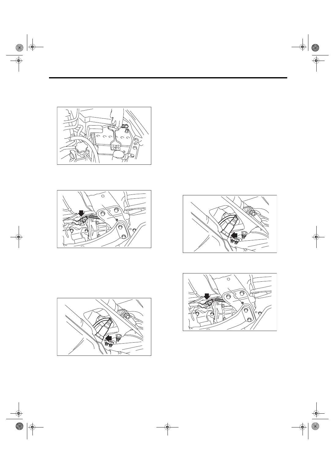
Rear Oxygen Sensor
FUEL INJECTION (FUEL SYSTEMS)
17.Rear Oxygen Sensor
A: REMOVAL
1) Disconnect the ground cable from battery.
2) Lift up the vehicle.
3) Disconnect the connector from the rear oxygen
sensor, and remove the clip (A) holding the rear ox-
ygen sensor harness.
4) Apply spray-type lubricant to the threaded por-
tion of rear oxygen sensor, and leave it for one
minute or more.
5) Remove the rear oxygen sensor.
CAUTION:
When removing the rear oxygen sensor, wait
until exhaust pipe cools, otherwise it will dam-
age the exhaust pipe.
B: INSTALLATION
CAUTION:
If lubricant is spilt onto the exhaust pipe, wipe it
off completely with cloth to avoid emission of
smoke or causing a fire.
1) Before installing rear oxygen sensor, apply the
anti-seize compound only to the threaded portion of
rear oxygen sensor to make the next removal eas-
ier.
CAUTION:
Never apply anti-seize compound to the protec-
tor of rear oxygen sensor.
Anti-seize compound:
NEVER-SEEZ NSN, JET LUBE SS-30 or
equivalent
2) Install the rear oxygen sensor.
Tightening torque:
21 N·m (2.1 kgf-m, 15.5 ft-lb)
3) Connect the connector to the rear oxygen sen-
sor, and hold the rear oxygen sensor harness with
the clip (A).
4) Lower the vehicle.
IN-00203
FU-04637
(A)
FU-04626
FU-04626
FU-04637
(A)