Subaru Impreza 3 / Impreza WRX / Impreza WRX STI. Manual - part 131
FU(w/o STI)-51
Wastegate Control Solenoid Valve
FUEL INJECTION (FUEL SYSTEMS)
15.Wastegate Control Solenoid
Valve
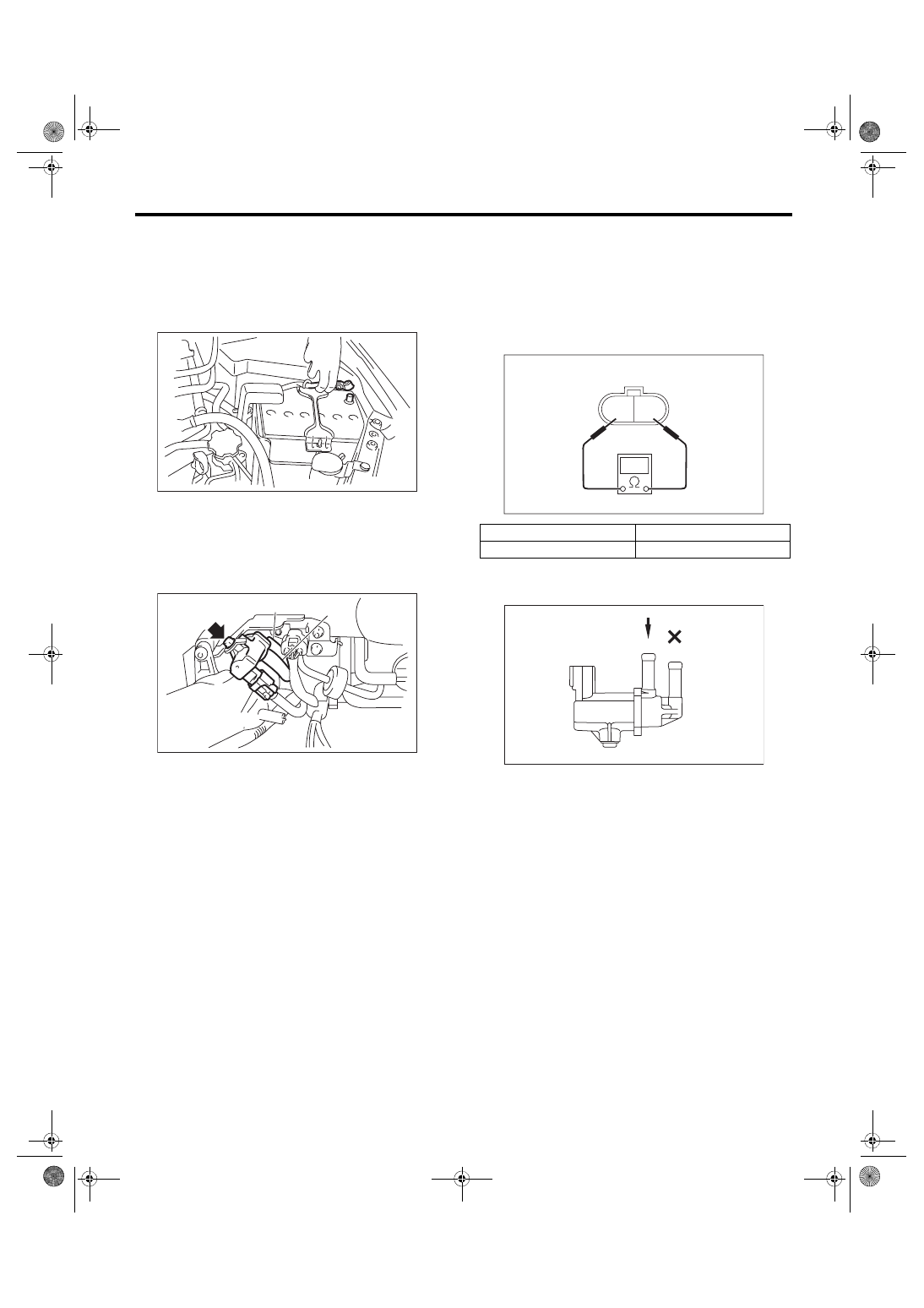
A: REMOVAL
1) Remove the collector cover.
2) Disconnect the ground cable from battery.
3) Disconnect the connector (A) from the waste-
gate control solenoid valve.
4) Disconnect the vacuum hose (B) and air control
hose (C) from the wastegate control solenoid valve.
5) Remove the wastegate control solenoid valve
from the bracket.
B: INSTALLATION
Install in the reverse order of removal.
Tightening torque:
6.4 N·m (0.7 kgf-m, 4.7 ft-lb)
C: INSPECTION
1. WASTEGATE CONTROL SOLENOID
VALVE
1) Check that the wastegate control solenoid valve
has no deformation, cracks or other damages.
2) Check the resistance between the wastegate
control solenoid valve terminals.
3) Check that air does not come out from (B) when
air is blown into (A).
IN-00203
FU-05739
(C)
(A)
(B)
Terminal No.
Standard
1 and 2
28±2 Ω (when 20°C (68°F))
2 1
EC-02426
FU-04069
(A)
(B)