Subaru Impreza 3 / Impreza WRX / Impreza WRX STI. Manual - part 130


  Index      Subaru     Subaru Impreza 3 / Impreza WRX / Impreza WRX STI - service repair manual 2008-2014 year


Search            


Content   ..  128  129  130  131   ..


Subaru Impreza 3 / Impreza WRX / Impreza WRX STI. Manual - part 130


FU(w/o STI)-47

Fuel Injector

FUEL INJECTION (FUEL SYSTEMS)

2. LH SIDE

Install in the reverse order of removal.
NOTE:

Use new O-rings, rubbers and seal rings.
Tightening torque:

6.4 N·m (0.7 kgf-m, 4.7 ft-lb)

Tightening torque:

19 N·m (1.9 kgf-m, 14.0 ft-lb)
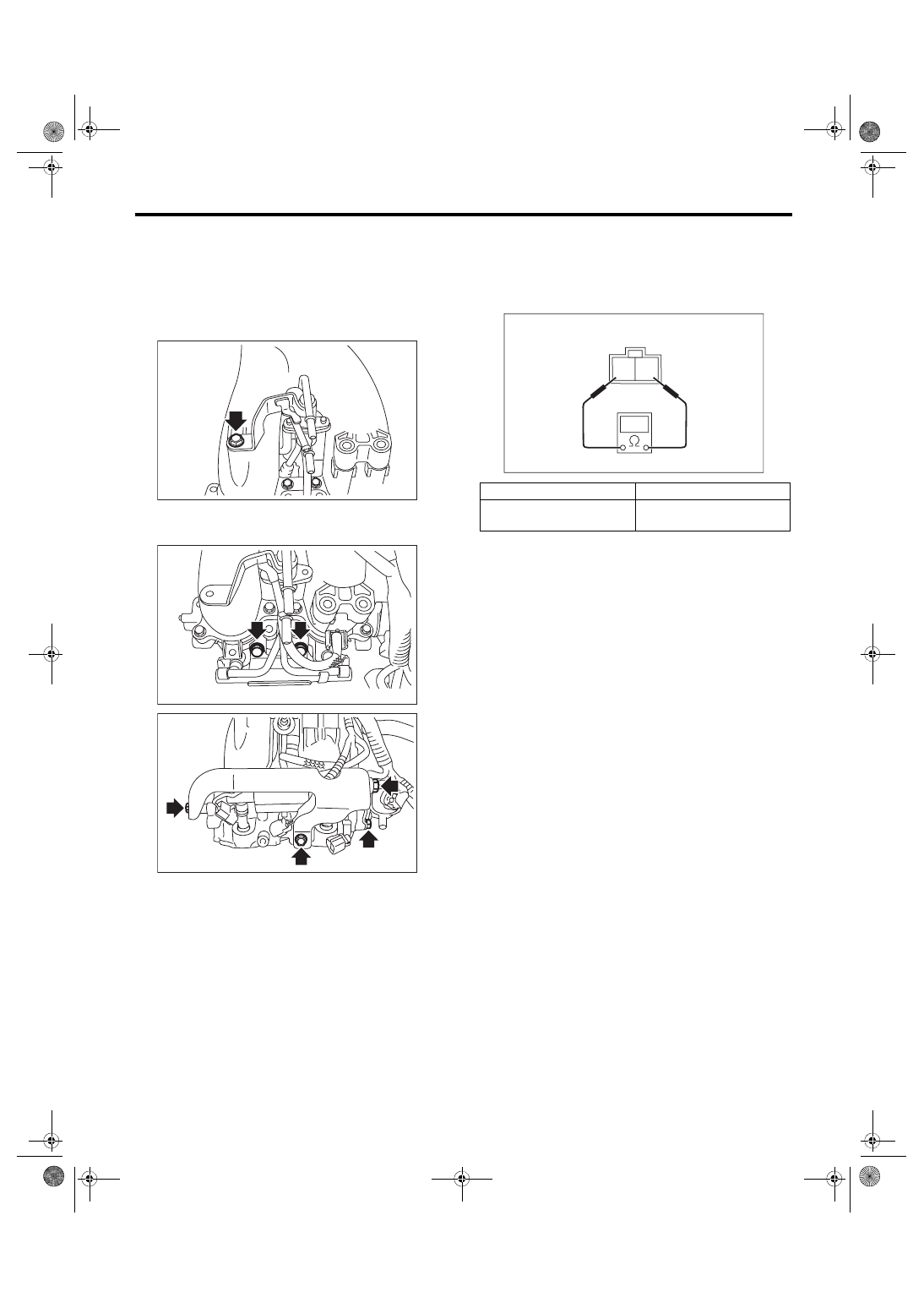
C: INSPECTION

1) Check that the fuel injector has no deformation,

cracks or other damages.

2) Measure  the  resistance  between  fuel  injector

terminals.

FU-05752

FU-04299

FU-06551

Terminal No.

Standard

1 and 2

Approx. 12.0 Ω 

(when 20°C (68°F))

2 1

EC-02428

FU(w/o STI)-48

Tumble Generator Valve Assembly

FUEL INJECTION (FUEL SYSTEMS)

12.Tumble Generator Valve As-

sembly

A: REMOVAL

1) Release the fuel pressure. <Ref. to FU(w/o STI)-

65, RELEASING OF FUEL PRESSURE, PROCE-

DURE, Fuel.>

2) Disconnect the ground cable from battery.

3) Open the fuel filler lid and remove the fuel filler

cap.

4) Remove  the  intake  manifold.  <Ref.  to  FU(w/o

STI)-18, REMOVAL, Intake Manifold.>

5) Disconnect the connector from the tumble gen-

erator valve assembly.

6) Remove the fuel injector. <Ref. to FU(w/o STI)-

45, REMOVAL, Fuel Injector.>

7) Remove  the  tumble  generator  valve  assembly

from the intake manifold.

B: INSTALLATION

Install in the reverse order of removal.
NOTE:

Use a new gasket.
Tightening torque:

8.3 N·m (0.8 kgf-m, 6.1 ft-lb)

C: INSPECTION

1) Check that the tumble generator valve assembly

has no deformation, cracks or other damages.

2) Check tumble generator valve for contamination

or clogging.

IN-00203

FU-05811

FU-04751

FU(w/o STI)-49

Tumble Generator Valve Actuator

FUEL INJECTION (FUEL SYSTEMS)

13.Tumble Generator Valve Ac-

tuator

A: SPECIFICATION

The  tumble  generator  valve  assembly  cannot  be

disassembled.

Refer  to  “Tumble  Generator  Valve  Assembly”  for

removal  and  installation  procedures.  <Ref.  to

FU(w/o  STI)-48,  REMOVAL,  Tumble  Generator

Valve  Assembly.>  <Ref.  to  FU(w/o  STI)-48,  IN-

STALLATION,  Tumble  Generator  Valve  Assem-

bly.>

FU(w/o STI)-50

Oil Flow Control Solenoid Valve

FUEL INJECTION (FUEL SYSTEMS)

14.Oil Flow Control Solenoid 

Valve

A: REMOVAL

Oil  flow  control  solenoid  valve  is  a  unit  with  front

camshaft cap.

Refer to “Camshaft” for removal procedures. <Ref.

to ME(w/o STI)-59, REMOVAL, Camshaft.>

B: INSTALLATION

Refer  to  “Camshaft”  for  installation  procedure.

<Ref.  to  ME(w/o  STI)-61,  INSTALLATION,  Cam-

shaft.>

C: DISASSEMBLY

1) Remove the two mounting bolts securing oil re-

turn  cover,  and  remove  the  oil  return  cover  and

gasket.

2) Remove the bolt securing oil flow control sole-

noid valve, and remove the oil flow control solenoid

valve.

D: ASSEMBLY

1) Install the oil flow control solenoid valve.
Tightening torque:

6.4 N·m (0.7 kgf-m, 4.7 ft-lb)

2) Apply liquid gasket to the two bolts securing oil

return cover.
Liquid gasket:

THREE BOND 1324 (Part No. 004403042) or 

equivalent

3) Attach the oil return cover and gasket.
NOTE:

Use a new gasket.
Tightening torque:

9 N·m (0.9 kgf-m, 6.6 ft-lb)

E: INSPECTION

1) Check that the oil flow control solenoid valve has

no deformation, cracks or other damages.

2) Measure  the  resistance  between  the  oil  flow

control solenoid valve terminals.

(A) Oil flow control solenoid valve
(B) Oil return cover

(C) Gasket
(D) Front camshaft cap

FU-05699

(A)

(D)

(C)

(B)

(A) Oil flow control solenoid valve
(B) Oil return cover

(C) Gasket
(D) Front camshaft cap

Terminal No.

Standard

1 and 2

7.4±0.5 Ω 

(when 20°C (68°F))

FU-05700

(A)

(D)

(C)

(B)

2 1

EC-02428


Content   ..  128  129  130  131   ..