Subaru Impreza 3 / Impreza WRX / Impreza WRX STI. Manual - part 128
FU(w/o STI)-39
Knock Sensor
FUEL INJECTION (FUEL SYSTEMS)
7. Knock Sensor
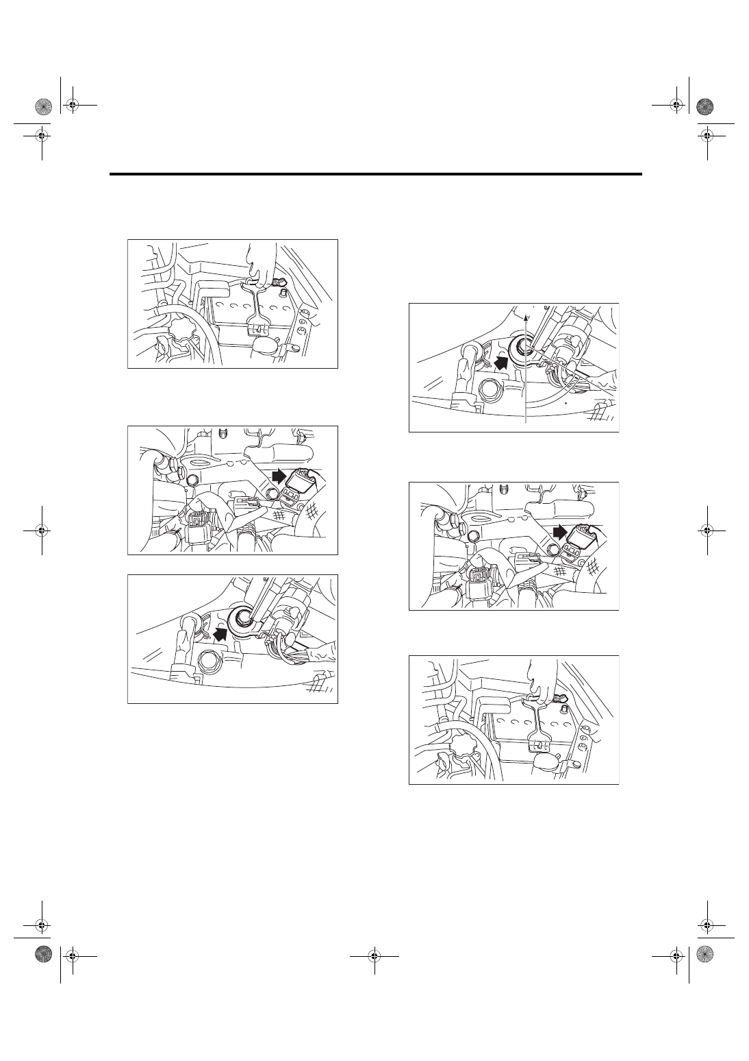
A: REMOVAL
1) Disconnect the ground cable from battery.
2) Remove the intercooler. <Ref. to IN(w/o STI)-12,
3) Disconnect the connector from the knock sen-
sor.
4) Remove the knock sensor from cylinder block.
B: INSTALLATION
1) Install the knock sensor to the cylinder block.
NOTE:
The portion of the knock sensor cord that is pulled
out must be positioned at a 60° angle relative to the
engine rear.
Tightening torque:
24 N·m (2.4 kgf-m, 17.7 ft-lb)
2) Connect the connector to the knock sensor.
3) Install the intercooler. <Ref. to IN(w/o STI)-12,
4) Connect the battery ground terminal.
IN-00203
FU-05716
FU-05750
(A) Front side of vehicle
FU-05751
(A)
60
FU-05716
IN-00203