Subaru Impreza 3 / Impreza WRX / Impreza WRX STI. Manual - part 123


  Index      Subaru     Subaru Impreza 3 / Impreza WRX / Impreza WRX STI - service repair manual 2008-2014 year


Search            


Content   ..  121  122  123  124   ..


Subaru Impreza 3 / Impreza WRX / Impreza WRX STI. Manual - part 123


FU(w/o STI)-19

Intake Manifold

FUEL INJECTION (FUEL SYSTEMS)

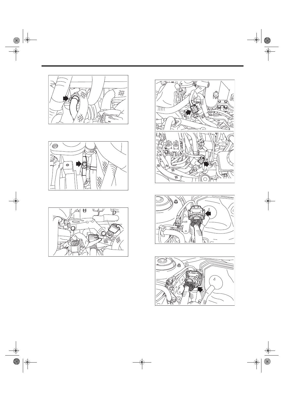
18) Disconnect the vacuum hose from nipple.

19) Disconnect  the  air  control  hose  (A)  from  the

waste gate actuator, and loosen the clamp which

holds the intake duct to the turbocharger.

20) Disconnect  the  connector  (A)  from  the  PCV

hose assembly A and the connector (B) from the

knock sensor.

21) Disconnect the connector from the PCV hose

assembly B and PCV hose assembly C.

22) Disconnect  the  bulkhead  harness  connectors

from the engine harness connectors.

23) Remove  the  engine  harness  connector  from

the engine harness bracket.

FU-05709

FU-05866

(A)

FU-05708

(A)

(B)

FU-06534

FU-06604

FU-06605

FU(w/o STI)-20

Intake Manifold

FUEL INJECTION (FUEL SYSTEMS)

24) Disconnect the connector (A) from the engine

coolant temperature sensor, connector (B) from the

oil  pressure  switch,  and  connector  (C)  from  the

crankshaft position sensor.

25) Disconnect the connector from power steering

pump switch.

26) Disconnect the connector from the secondary

air combination valve.

27) Disconnect the connector from camshaft posi-

tion sensor.

28) Disconnect the connector from the oil flow con-

trol solenoid valve.

29) Lift up the vehicle.

FU-05711

(C)

(B)

(A)

FU-04598

FU-05712

FU-04616

FU-06535

FU(w/o STI)-21

Intake Manifold

FUEL INJECTION (FUEL SYSTEMS)

30) Disconnect the connector from ignition coil.

31) Lower the vehicle.

32) Disconnect the connector from the front oxygen

(A/F) sensor, and remove the clip (A) and stay (B)

which hold the engine harness to the rocker cover

RH.

33) Attach ST to the fuel delivery pipe and push ST

in the direction of arrow mark to disconnect the fuel

delivery hose.

ST 42099AE000 QUICK CONNECTOR RE-

LEASE

CAUTION:

• Be careful not to spill fuel.

• Catch the fuel from hoses using a container

or cloth.

34) Disconnect the fuel return hose using the ST.

ST 18371AA000 CONNECTOR REMOVER
CAUTION:

• Be careful not to spill fuel.

• Catch the fuel from hoses using a container

or cloth.

(1) Attach ST to the fuel return pipe as shown in

the figure.

FU-06536

FU-05714

(A)

(B)

(A) Fuel delivery hose
(B) Fuel return hose

(C) Evaporation hose

FU-06537

(C)

ST

(B)

(A)

ME-04969

ST

FU(w/o STI)-22

Intake Manifold

FUEL INJECTION (FUEL SYSTEMS)

(2) Insert the front side of ST into the quick con-

nector.

(3) Insert the back side of ST into the quick con-

nector  and  push  ST  in  the  direction  of  arrow

mark to disconnect the fuel return hose.

35) Remove the clip and disconnect the evapora-

tion hose from the fuel pipe.

36) Remove  the  intake  manifold  from  cylinder

head.

B: INSTALLATION

1) Install the intake manifold onto cylinder heads.
NOTE:

Use a new gasket.
Tightening torque:

25 N·m (2.5 kgf-m, 18.4 ft-lb)

ME-04970

ST

ME-04971

ST

FU-04611

FU-06538

FU-06538


Content   ..  121  122  123  124   ..