Subaru Impreza 3 / Impreza WRX / Impreza WRX STI. Manual - part 124


  Index      Subaru     Subaru Impreza 3 / Impreza WRX / Impreza WRX STI - service repair manual 2008-2014 year


Search            


Content   ..  122  123  124  125   ..


Subaru Impreza 3 / Impreza WRX / Impreza WRX STI. Manual - part 124


FU(w/o STI)-23

Intake Manifold

FUEL INJECTION (FUEL SYSTEMS)

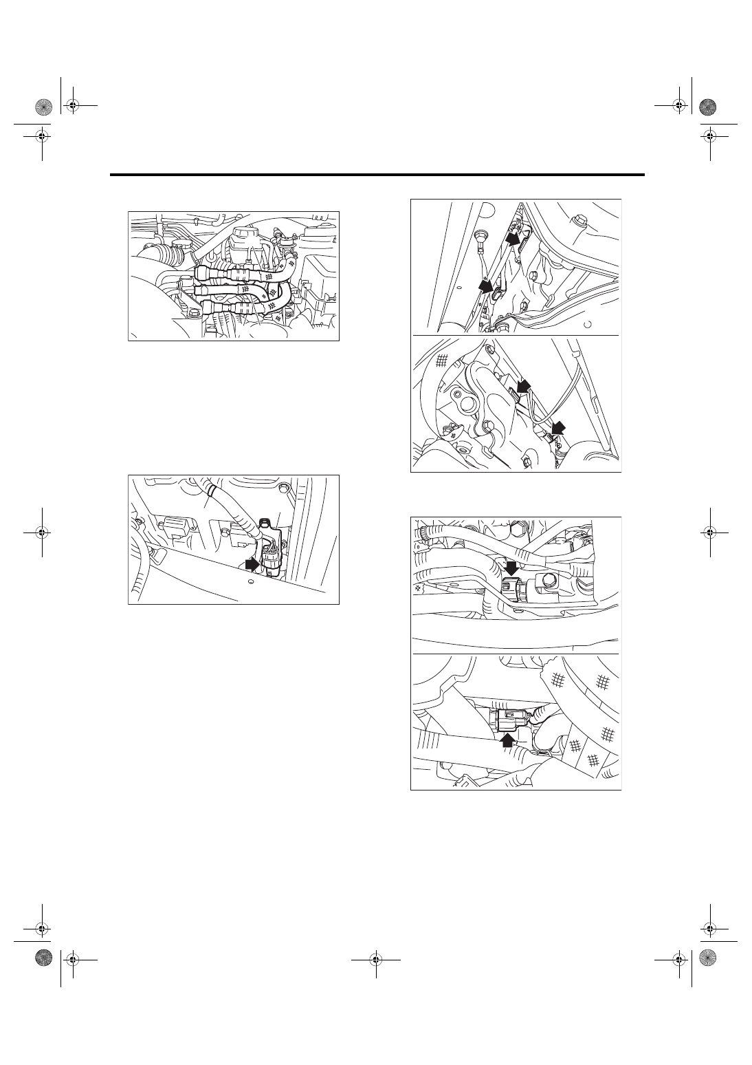
2) Connect the fuel delivery hose, fuel return hose,

and evaporation hose.

3) Connect the front oxygen (A/F) sensor connec-

tor,  and  secure  the  engine  harness  to  the  rocker

cover RH with clip (A) and stay (B).
Tightening torque:

6.4 N·m (0.7 kgf-m, 4.7 ft-lb)

4) Lift up the vehicle.

5) Connect the connector to the ignition coil.

6) Lower the vehicle.

7) Connect  the  connector  to  oil  flow  control  sole-

noid valve.

(A) Fuel delivery hose
(B) Fuel return hose

(C) Evaporation hose

FU-06721

(C)

(B)

(A)

FU-05714

(A)

(B)

FU-06536

FU-06535

FU(w/o STI)-24

Intake Manifold

FUEL INJECTION (FUEL SYSTEMS)

8) Connect  the  connectors  to  camshaft  position

sensor.

9) Connect the connector to the secondary air com-

bination valve.

10) Connect  the  connector  to  the  power  steering

pump switch.

11) Connect the connector (A) to the engine cool-

ant  temperature  sensor,  connector  (B)  to  the  oil

pressure  switch,  and  the  connector  (C)  to  the

crankshaft position sensor.

12) Install the engine harness connector to engine

harness  bracket,  then  connect  the  bulkhead  har-

ness connector to the engine harness connector.

FU-04616

FU-05712

FU-04598

FU-05711

(C)

(B)

(A)

FU-06604

FU(w/o STI)-25

Intake Manifold

FUEL INJECTION (FUEL SYSTEMS)

13) Connect  the  connector  to  the  PCV  hose  as-

sembly B and PCV hose assembly C.

14) Connect the connector (A) to the PCV hose as-

sembly A and the connector (B) to the knock sen-

sor.

15) Connect the air control hose (A) to the waste-

gate actuator, and install the turbocharger to the in-

take duct.
Tightening torque:

3 N·m (0.3 kgf-m, 2.2 ft-lb)

16) Connect the vacuum hose to the nipple.

17) Connect  the  engine  coolant  hoses  to  throttle

body.

18) Install the intake duct to the throttle body, and

install the bolts which secure the PCV pipe assem-

bly to the intake manifold.
Tightening torque:

T1: 3 N·m (0.3 kgf-m, 2.2 ft-lb)

T2: 6.4 N·m (0.7 kgf-m, 4.7 ft-lb)

FU-06534

FU-05708

(A)

(B)

FU-05866

(A)

FU-05709

FU-05669

T2

T1

FU-06539

FU(w/o STI)-26

Intake Manifold

FUEL INJECTION (FUEL SYSTEMS)

19) Install  the  bolts  which  secure  the  air  bypass

pipe  to  the  intake  manifold,  and  install  the  brake

booster vacuum hose to the clip (A).
Tightening torque:

6.4 N·m (0.7 kgf-m, 4.7 ft-lb)

20) Connect the brake booster vacuum hose.

21) Install the A/C pressure hoses to A/C compres-

sor.  <Ref.  to  AC-41,  INSTALLATION,  Hose  and

Pipe.>

22) Install the coolant filler tank. <Ref. to CO(w/o

STI)-28, INSTALLATION, Coolant Filler Tank.>

23) Install the generator. <Ref. to SC(STI)-21, IN-

STALLATION, Generator.>

24) Install the intercooler. <Ref. to IN(w/o STI)-12,

INSTALLATION, Intercooler.>

25) Install the air intake duct and air cleaner case.

<Ref. to IN(w/o STI)-8, INSTALLATION, Air Clean-

er  Case.>  <Ref.  to  IN(w/o  STI)-10,  INSTALLA-

TION, Air Intake Duct.>

26) Connect the battery ground terminal.

27) Lift up the vehicle.

28) Install the under cover. <Ref. to EI-28, INSTAL-

LATION, Front Under Cover.>

29) Lower the vehicle.

30) Fill  engine  coolant.  <Ref.  to  CO(w/o  STI)-13,

FILLING  OF  ENGINE  COOLANT,  REPLACE-

MENT, Engine Coolant.>

31) Charge the A/C system with refrigerant. <Ref.

to  AC-20,  PROCEDURE,  Refrigerant  Charging

Procedure.>

32) Install the V-belt cover.
Tightening torque:

13 N·m (1.3 kgf-m, 9.6 ft-lb)

C: DISASSEMBLY

1) Remove the fuel pipe protector RH from the in-

take manifold.

2) Remove  the  engine  ground  terminal  from  the

fuel pipe protector LH and remove the fuel pipe pro-

tector LH from the intake manifold.

3) Disconnect  the  vacuum  hose  (A)  from  intake

manifold.

FU-06527

(A)

FU-06533

IN-00203

ME-03386

FU-06561

FU-06540


Content   ..  122  123  124  125   ..