Subaru Impreza 3 / Impreza WRX / Impreza WRX STI. Manual - part 117


  Index      Subaru     Subaru Impreza 3 / Impreza WRX / Impreza WRX STI - service repair manual 2008-2014 year


Search            


Content   ..  115  116  117  118   ..


Subaru Impreza 3 / Impreza WRX / Impreza WRX STI. Manual - part 117


SC(STI)-24

Generator

STARTING/CHARGING SYSTEMS

(3) Disconnect the connection and remove the

brush.

10) Remove the rectifier as follows.

(1) Remove the bolts which secure the rectifier.

(2) Remove the cover on terminal B.

(3) Remove the nuts of terminal B, then remove

the rectifier.

D: ASSEMBLY

Assemble in the reverse order of disassembly.
NOTE:

• Refer to component for tightening torque of each

part. <Ref. to SC(STI)-5, GENERATOR, COMPO-

NENT, General Description.>

• After  assembling,  manually  turn  the  pulley  to

check that the rotor rotates smoothly.

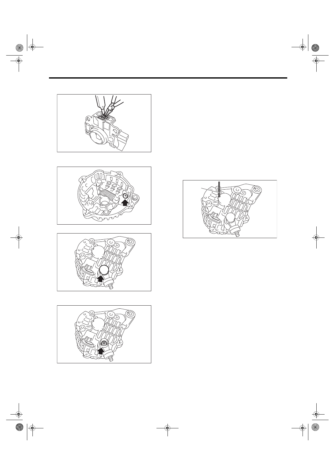
1) Push of the brush

Before assembling the front and rear parts, press

the brush down into the brush holder, then fix the

brush  in  that  position  by  inserting  a  wire  [1  mm

(0.08  in)  dia.,  40  —  50  mm  (1.6  —  2.0  in)  long]

through the hole as shown in the figure.
CAUTION:

After assembling, remove the wire.

2) Install the ball bearings

(1) Set the ball bearings in the front cover, then

securely install an appropriate tool (such as a

socket  wrench  of  proper  size)  to  the  bearing

outer race.

(2) Using a press to press the ball bearings into

the specified location.

(3) Install the bearing retainer.

3) Install the bearings.
CAUTION:

Do not apply grease to the bearings. If there is

any oil on the bearing box, remove it complete-

ly.

(1) Use a press to install the bearings to the ro-

tor shaft.

(2) Heat the bearing box in rear cover at 50 to

60°C (122 to 140°F), and then press the bear-

ing into rear cover.

SC-00088

SC-00089

SC-00090

SC-00091

(A) Wire

SC-00092

(A)

SC(STI)-25

Generator

STARTING/CHARGING SYSTEMS

E: INSPECTION

1. DIODE

CAUTION:

There is the possibility of damaging the diodes

if a mega-tester (used to measure high voltag-

es) or a similar measuring instrument is used.

Never use a mega tester or equivalent for this

test.

1) Check for continuity between the diode lead and

positive side heat sink. If resistance is 1 Ω or more

only in the direction from the diode lead to the heat

sink, replace the rectifier.

2) Check for continuity between the negative side

heat  sink  and  diode  lead.  If  resistance  is  1  Ω  or

more only in the direction from the heat sink to the

diode lead, replace the rectifier.

2. ROTOR

1) Inspect  the  slip  rings  for  contamination  or  any

roughness  on  the  sliding  surface.  Repair  the  slip

ring surface using a lathe or sand paper.

2) Measure  the  slip  ring  outer  diameter.  Replace

the rotor if the slip ring is worn.
Slip ring outer diameter:

Standard

22.7 mm (0.894 in)

Limit

22.1 mm (0.870 in)

3) Using a circuit tester, check the resistance be-

tween  slip  rings.  If  resistance  exceeds  the  stan-

dard, replace the rotor.
Standard:

Approx. 1.8 — 2.2 

Ω

4) Check the continuity between slip ring and rotor

core or shaft. If there is continuity, replace the rotor

because the rotor coil is grounded.

5) Check the bearings. If there is any noise, or the

rotor  does  not  rotate  smoothly,  replace  the  bear-

ings.

(A) Diode lead
(B) Heat sink (positive side)

(A) Diode lead
(B) Heat sink (negative side)

SC-00042

(B)

(A)

(A)

(B)

SC-00043

SC-00044

SC-00045

SC(STI)-26

Generator

STARTING/CHARGING SYSTEMS

3. STATOR COIL

1) Inspect  continuity  between  the  stator  coil  lead

wire terminals. If the resistance is 1 MΩ or more, re-

place the stator coil.

2) Inspect the continuity between the stator coil sta-

tor core and lead wire terminals. If the resistance is

1 Ω or less, replace the stator coil.

4. BRUSH

1) Measure the length of each brush. Replace the

brush if wear exceeds service limits. There is a ser-

vice limit mark (A) on each brush.
Brush length:

Standard (1)

18.5 mm (0.728 in)

Limit (2)

5.0 mm (0.197 in)

2) Using  a  spring  pressure  indicator,  push  the

brush into the brush holder until its tip protrudes 2

mm (0.08 in). Then measure the pressure of brush

spring. If the pressure is 2.648 N (270 g, 9.52 oz) or

less,  replace  the  brush  spring  with  a  new  part.

4.609 — 5.786 N (470 — 590 g, 16.58 — 20.810

oz) pressure is required on the new spring.

5. BALL BEARING

Check the ball bearings. Replace the ball bearings

if there is resistance in the rotation, or if there is any

abnormal noise.

6. OTHER INSPECTIONS

Check that the generator does not have deforma-

tion, cracks and any other damage.

(A) Stator coil

(A)

SC-00047

SC-00048

SC-02313

(A)

(1)

(2)

SC-00093

SC(STI)-27

Battery

STARTING/CHARGING SYSTEMS

4. Battery

A: REMOVAL

1) Disconnect the positive (+) terminal after discon-

necting the negative (–) terminal of battery.

2) Remove the harness clip of the negative termi-

nal from the battery rod.

3) Remove the flange nut from battery rod and re-

move battery holder.

4) Remove the battery.

B: INSTALLATION

Install in the reverse order of removal.
Tightening torque:

3.5 N·m (0.4 kgf-m, 2.6 ft-lb)

NOTE:

• Clean  the  battery  cable  terminals  and  apply

grease to retard the formation of corrosion.

• Connect the positive (+) terminal, and then con-

nect the negative (–) terminal of the battery.

• After the  battery  is installed, initial diagnosis of

the electronic throttle control is performed. Wait for

10 seconds or more after turning the ignition switch

to ON, and then start the engine.

C: INSPECTION

WARNING:

• Electrolyte is corrosive acid, and has toxici-

ty; be careful of handling the fluid.

• Make sure the electrode does not come into

contact with skin, eyes or clothing. Especially

at  contact  with  eyes,  flush  with  water  for  15

minutes and get prompt medical attention.

• In addition, be careful not to let the electrode

contact with the coated parts.

• Be  careful  when  handling  the  batteries  be-

cause they produce explosive gases.

• Be sure to keep battery away from any fire.

• For safety, in case an explosion does occur,

wear eye protection or shield your eyes when

working  near  any  battery.  In  addition,  never

lean over the battery.

• Ventilate sufficiently when using or charging

battery in enclosed space.

• Before  starting  work,  remove  rings,  metal

watch-bands, and other metal jewelry.

• Never allow metal tools to contact the posi-

tive battery terminal and anything connected to

it while you are at the same time in contact with

any other metallic portion of the vehicle.

1. EXTERNAL PARTS

Check the battery case, top cover, vent plugs, and

terminal posts for dirt or cracks. If necessary, clean

with water and wipe with a dry cloth.

Apply a thin coat of grease on the terminal posts to

prevent corrosion.

2. ELECTROLYTE LEVEL

Check the electrolyte level in each cell. If the level

is below MIN level, bring the level to MAX level by

pouring distilled water into the battery cell. Do not

fill beyond MAX level.

3. SPECIFIC GRAVITY OF ELECTROLYTE

1) Measure  specific  gravity  of  electrolyte  using  a

hydrometer and a thermometer.

Specific gravity varies with temperature of electro-

lyte so that it must be corrected at 20°C (68°F) us-

ing the following calculation:
S

20

 = St + 0.0007 × (t – 20)

S

20

: Specific gravity corrected at electrolyte 

temperature of 20°C (68°F)

St: Measured specific gravity

t: Measured temperature (°C)

Judge whether or not the battery requires 

charging according to corrected specific 

gravity.

Standard specific gravity: 1.220 — 1.290 [at 

20°C (68°F)]

SC-02238


Content   ..  115  116  117  118   ..