Subaru Impreza 3 / Impreza WRX / Impreza WRX STI. Manual - part 44


  Index      Subaru     Subaru Impreza 3 / Impreza WRX / Impreza WRX STI - service repair manual 2008-2014 year


Search            


Content   ..  42  43  44  45   ..


Subaru Impreza 3 / Impreza WRX / Impreza WRX STI. Manual - part 44


FU(STI)-88

Fuel Filter

FUEL INJECTION (FUEL SYSTEMS)

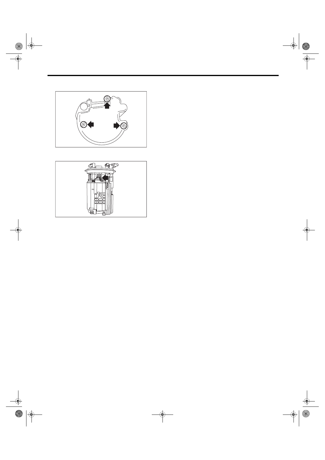
7) Replace the cushion on the rear face of the sub

tank with a new cushion.

8) Connect  the  pump  assembly  connector  to  the

sub tank bracket assembly.

9) Install the fuel level sensor. <Ref. to FU(STI)-82,

INSTALLATION, Fuel Level Sensor.>

10) Inspect the fuel level sensor. <Ref. to FU(STI)-

82, INSPECTION, Fuel Level Sensor.>

11) Install  the  fuel  pump  assembly.  <Ref.  to

FU(STI)-81, INSTALLATION, Fuel Pump.>

FU-03863

FU-03849

FU(STI)-89

Pulsation Damper Assembly

FUEL INJECTION (FUEL SYSTEMS)

31.Pulsation Damper Assembly

A: REMOVAL

WARNING:

Place  “NO  OPEN  FLAMES”  signs  near  the

working area.
CAUTION:

• Be careful not to spill fuel.

• Catch the fuel from hoses using a container

or cloth.

1) Release the fuel pressure. <Ref. to FU(STI)-67,

RELEASING  OF  FUEL  PRESSURE,  PROCE-

DURE, Fuel.>

2) Disconnect  the  fuel  delivery  hose  (A)  and  fuel

hose (B) from the pulsation damper assembly, and

remove the pulsation damper assembly.

B: INSTALLATION

Install in the reverse order of removal.
NOTE:

For the information about connecting the fuel deliv-

ery hose and fuel hose, refer to “Fuel Delivery, Re-

turn  &  Evaporation  Lines”.  <Ref.  to  FU(STI)-97,

CONNECTING  FUEL  DELIVERY  HOSE,  FUEL

RETURN  HOSE  AND  FUEL  HOSE,  INSTALLA-

TION,  Fuel  Delivery,  Return  and  Evaporation

Lines.>

C: DISASSEMBLY

Remove the pulsation damper and fuel pipe gasket

from the fuel by-pass pipe.

D: ASSEMBLY

Install the fuel pipe gasket and pulsation damper to

the fuel by-pass pipe.
NOTE:

Use a new fuel pipe gasket.
Tightening torque:

21.6 N·m (2.2 kgf-m, 15.9 ft-lb)

E: INSPECTION

1) Check that the pulsation damper assembly has

no deformation, cracks or other damages.

2) Check that the fuel delivery hose and fuel hose

have no cracks, damage or loose part.

FU-05794

(A)

(B)

(A)

(A) Fuel by-pass pipe
(B) Pulsation damper

(C) Fuel pipe gasket

(A) Fuel by-pass pipe
(B) Pulsation damper

(C) Fuel pipe gasket

FU-06743

(C)

(B)

(A)

FU-06744

(C)

(B)

(A)

FU(STI)-90

Pressure Regulator & Damper Assembly

FUEL INJECTION (FUEL SYSTEMS)

32.Pressure Regulator & Damp-

er Assembly

A: REMOVAL

WARNING:

Place  “NO  OPEN  FLAMES”  signs  near  the

working area.
CAUTION:

• Be careful not to spill fuel.

• Catch the fuel from hoses using a container

or cloth.

1) Release the fuel pressure. <Ref. to FU(STI)-67,

RELEASING  OF  FUEL  PRESSURE,  PROCE-

DURE, Fuel.>

2) Disconnect the vacuum hose (A) from the pres-

sure regulator and damper assembly.

3) Disconnect  the  fuel  return  hose  (B)  and  fuel

hose (C) from the pressure regulator & damper as-

sembly,  and  remove  the  fuel  regulator  &  damper

assembly.

B: INSTALLATION

Install in the reverse order of removal.
NOTE:

For the information about connecting the fuel return

hose and fuel hose, refer to “Fuel Delivery, Return

& Evaporation Lines”. <Ref. to FU(STI)-97, CON-

NECTING  FUEL  DELIVERY  HOSE,  FUEL  RE-

TURN HOSE AND FUEL HOSE, INSTALLATION,

Fuel Delivery, Return and Evaporation Lines.>

C: DISASSEMBLY

1) Remove  the  fuel  pipe  protector  from  the  pres-

sure regulator and damper assembly.

2) Remove the pulsation damper and fuel pipe gas-

ket from the fuel holder assembly, and remove the

pressure regulator from the fuel holder assembly.

FU-05795

(A)

(C)

(B)

(B)

(A) Pressure regulator & damper ASSY
(B) Fuel pipe protector

(A) Fuel holder ASSY
(B) Pulsation damper

(C) Fuel pipe gasket
(D) Pressure regulator

(E) O-ring

FU-06745

(A)

(B)

(C)

(B)

(A)

(D)

(E)

FU-06746

FU(STI)-91

Pressure Regulator & Damper Assembly

FUEL INJECTION (FUEL SYSTEMS)

D: ASSEMBLY

1) Install the pressure regulator to the fuel holder

assembly, and install the fuel pipe gasket and pul-

sation damper to the fuel holder assembly.
NOTE:

• Use new O-rings and fuel pipe gaskets.

• Apply  a  thin  coat  of  engine  oil  to  the  pressure

regulator installation hole of fuel holder assembly.
Tightening torque:

T1: 6.4 N·m (0.7 kgf-m, 4.7 ft-lb)

T2: 21.6 N·m (2.2 kgf-m, 15.9 ft-lb)

2) Install the fuel pipe protector to the pressure reg-

ulator and damper assembly.

E: INSPECTION

1) Check  that  the  pressure  regulator  and  damper

assembly has no deformation, cracks or other dam-

ages.

2) Check  that  the  vacuum  hose,  fuel  return  hose

and  fuel  hose  have  no  cracks,  damage  or  loose

part.

(A) Fuel holder ASSY
(B) Pulsation damper

(C) Fuel pipe gasket
(D) Pressure regulator

(E) O-ring

(A) Pressure regulator & damper ASSY
(B) Fuel pipe protector

(C)

(B)

(A)

(D)

(E)

T1

T2

FU-06747

FU-06745

(A)

(B)


Content   ..  42  43  44  45   ..