Subaru Impreza 3 / Impreza WRX / Impreza WRX STI. Manual - part 43
 

  Index      Subaru     Subaru Impreza 3 / Impreza WRX / Impreza WRX STI - service repair manual 2008-2014 year


Search            


Content   ..  41  42  43  44   ..


Subaru Impreza 3 / Impreza WRX / Impreza WRX STI. Manual - part 43


FU(STI)-84

Fuel Sub Level Sensor

FUEL INJECTION (FUEL SYSTEMS)

B: INSTALLATION

Install in the reverse order of removal while being

careful of the following.

• Make sure the sealing portion is free from fuel or

foreign matter before installation.

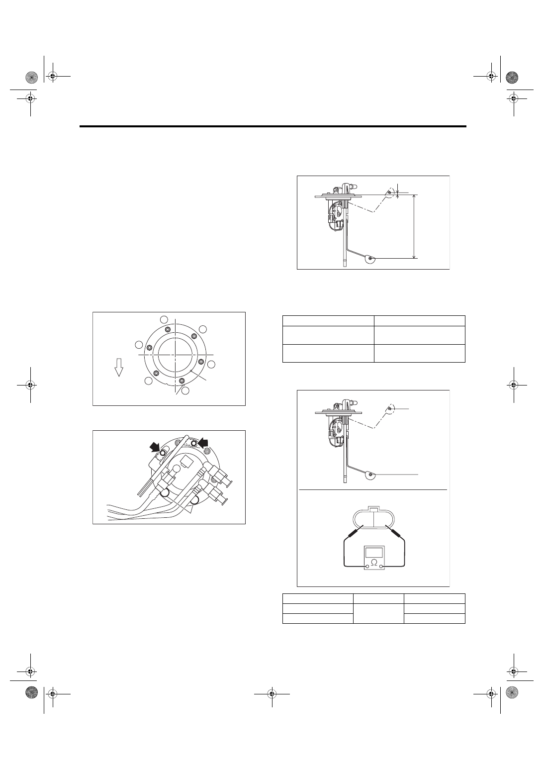
• Align protrusion (A) of the gasket to the position

shown in the figure.

• Align protrusion (B) of the fuel sub level sensor to

the cutout in the fuel sub level sensor upper plate.

• Tighten the nuts and bolts to the specified torque

in the order as shown in the figure.

• After tightening, install the rubber cap (C) at the

position shown in the figure.
NOTE:

• Use a new gasket.

• Do not forget to install rubber cap (C).
Tightening torque:

4.4 N·m (0.4 kgf-m, 3.2 ft-lb)

C: INSPECTION

1) Check that the fuel sub level sensor has no dam-

age.

2) Measure the fuel sub level sensor float position.

3) Measure the resistance between fuel sub level

sensor terminals.

(a) Front side of vehicle

FU-04533

1

6

5

2

4

3

(B)

(A)

(a)

FU-04242

(C)

(1) FULL
(2) EMPTY
(3) Datum points

Float position

Standard

FULL to Datum point (A)

5.31±3.5 mm 

(0.209±0.138 in)

EMPTY to Datum point (B)

160.6±3.5 mm 

(6.323±0.138 in)

Float position

Terminal No.

Standard

FULL (A)

1 and 2

2.0

+0.5


–1.0

 Ω

EMPTY (B)

62.1±1.0 Ω

(1)

(B)

(2)

(A)

FU-04213

(3)

FU-04214

2 1

(B)

(A)

FU(STI)-85

Fuel Filter

FUEL INJECTION (FUEL SYSTEMS)

30.Fuel Filter

A: REMOVAL

WARNING:

Place  “NO  OPEN  FLAMES”  signs  near  the

working area.
CAUTION:

• Be careful not to spill fuel.

• If the fuel gauge indicates that two thirds or

more of the fuel is remaining, be sure to drain

fuel  before  starting  work  to  avoid  the  fuel  to

spill.

• Be careful not to drop or apply any impact to

the  fuel  pump  during  work.  This  may  deterio-

rate its performance.
NOTE:

The fuel filter is built in fuel pump assembly.

1) Remove  the  fuel  pump  assembly.  <Ref.  to

FU(STI)-80, REMOVAL, Fuel Pump.>

2) Remove the fuel level sensor. <Ref. to FU(STI)-

82, REMOVAL, Fuel Level Sensor.>

3) Disconnect the pump assembly connector from

sub tank bracket assembly.

4) Cut off the tab holders connecting the sub tank

bracket  assembly  and  the  sub  tank  in  four  loca-

tions, and separate the sub tank bracket assembly

and the sub tank.
CAUTION:

Be careful not to damage the sub tank.
NOTE:

If the O-ring is remaining on the sub tank, remove.

5) Disconnect two connectors of fuel delivery pipe

from fuel filter assembly.

6) Push to compress the fuel filter assembly in the

direction of the arrow, remove clip (A), and sepa-

rate the sub tank bracket assembly and the fuel fil-

ter assembly.
CAUTION:

When separating the sub tank bracket assem-

bly and the fuel filter assembly, be careful not

to damage the ground wire.

7) Disconnect the connector from the pump assem-

bly.

FU-03849

FU-03850

FU-05678

FU-03852

(A)

FU-03853

FU(STI)-86

Fuel Filter

FUEL INJECTION (FUEL SYSTEMS)

8) Lift the two tab holders connecting the pump as-

sembly to the fuel filter using a flat tip screwdriver

(with a shaft diameter of approx. 3 mm (0.12 in)),

etc., and separate the fuel filter and pump assem-

bly.
CAUTION:

• To  prevent  damaging  the  tabs  of  the  pump

assembly,  wrap  the  tip  of  flat  tip  screwdriver

(A), etc. with tape (B).

• Be careful not to drop or apply any impact to

the pump assembly.
NOTE:

If the spacer and O-ring are remaining on the pump

assembly, remove them.

B: INSTALLATION

1) Assemble O-ring (A) and spacer (B) to the pump

assembly and attach the pump assembly to the fuel

filter.
NOTE:

• Use new O-rings (8 mm (0.31 in) inner diameter).

• Use a new spacer.

• Apply gasoline to the O-ring.

• Insert the pump assembly until a click is heard.

2) Connect the connector to the pump assembly.

FU-03929

(B)

(A)

FU-03927

(A)

(B)

FU-03859

FU-03853

FU(STI)-87

Fuel Filter

FUEL INJECTION (FUEL SYSTEMS)

3) Attach spring (A) to the metal rod of the sub tank

bracket assembly, and assemble the fuel filter as-

sembly.
NOTE:

Use a new spring.

4) Push the fuel filter assembly in the direction of

the arrow to compress, and attach clip (A).
NOTE:

Use a new clip.

5) Connect the fuel piping connector to the fuel fil-

ter assembly.
NOTE:

• Use new O-rings.

• Apply gasoline to the O-ring.

• The  O-rings  of  the  black  and  white  connectors

are identified by a difference in diameter. Be careful

not to confuse the two during assembly.
O-ring inner diameter:

Black connector O-ring [Approx. 7 mm (0.28 

in)]

White connector O-ring [Approx. 8 mm (0.31 

in)]

6) Attach the O-ring (A) to the fuel filter assembly,

and attach the sub tank to the sub tank bracket as-

sembly.
NOTE:

• Use new O-rings (8 mm (0.31 in) inner diameter).

• Apply gasoline to the O-ring.

• Insert the pump assembly until a “pop” is heard.

FU-03860

(A)

(A)

FU-03861

(A)

FU-05678

FU-03862

(A)


Content   ..  41  42  43  44   ..