Subaru Impreza 3 / Impreza WRX / Impreza WRX STI. Manual - part 31
FU(STI)-36
Crankshaft Position Sensor
FUEL INJECTION (FUEL SYSTEMS)
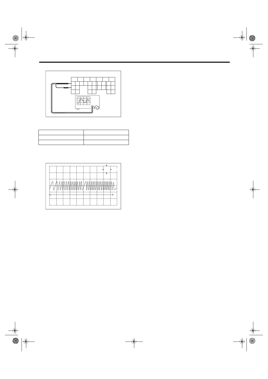
6) Connect the probe to ECM connector.
7) Start the engine and let it idle.
8) Check the pattern is the same as the waveform
and voltage shown below.
9) After inspection, install the related parts in the
reverse order of removal.
Tightening torque:
7.5 N·m (0.8 kgf-m, 5.5 ft-lb)
3. OTHER INSPECTIONS
Check that the crankshaft position sensor has no
deformation, cracks or other damages.
(A) To ECM connector
Terminal No.
Probe
17
+
25
–
(A) One crankshaft rotation
5
6
7
8
2
1
9
4
3
10
22
23
11
12
13
14
15
24
25
26
16
17
18
19
20
21
27
28
29
30
31
FU-04758
(A)
FU-04057
5V
0
10ms
(A)