Subaru Impreza 3 / Impreza WRX / Impreza WRX STI. Manual - part 29
FU(STI)-28
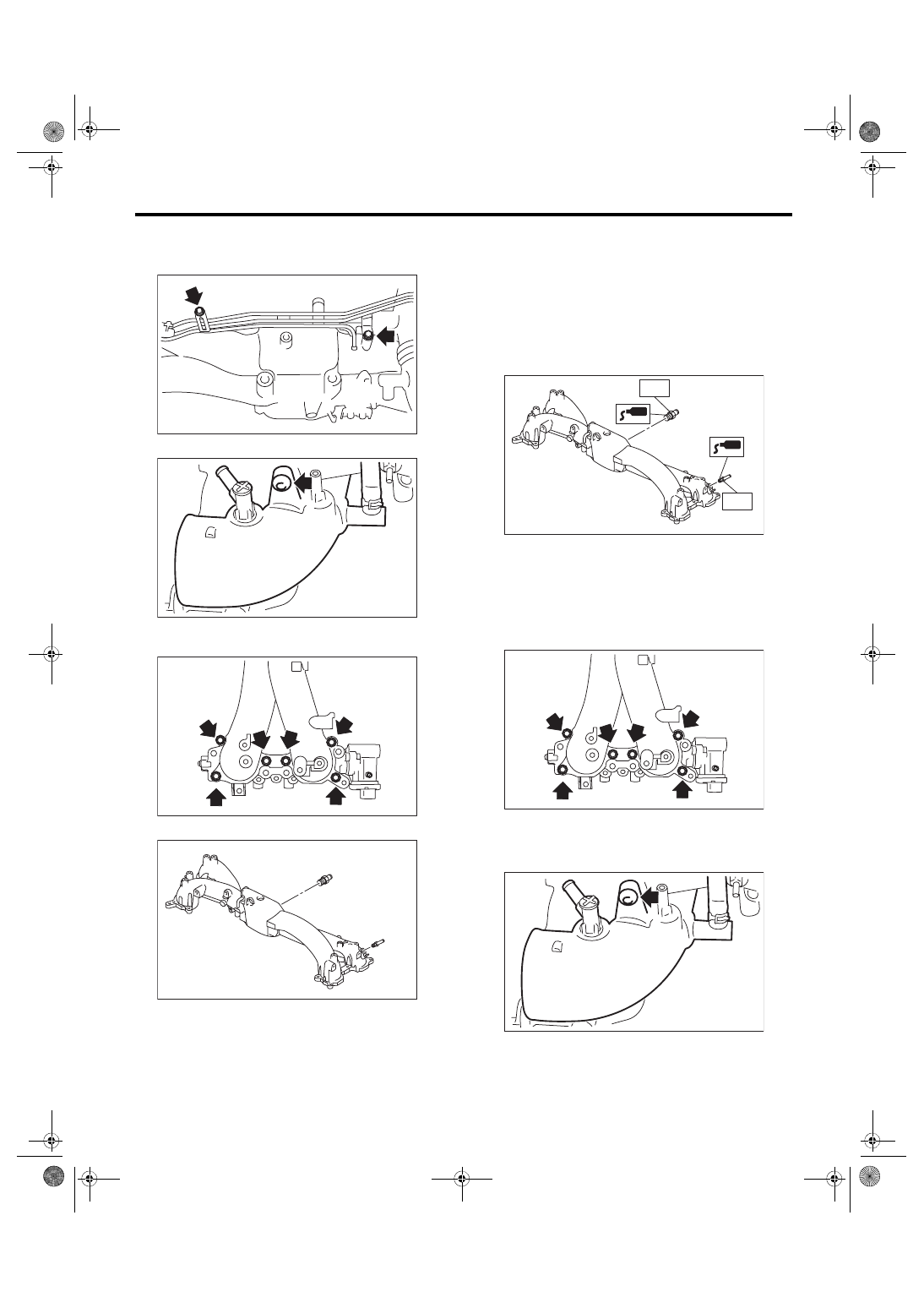
Intake Manifold
FUEL INJECTION (FUEL SYSTEMS)
20) Remove the bolts holding the fuel pipe assem-
bly to the intake manifold, and remove the fuel pipe
assembly.
21) Remove the intake duct from intake manifold.
22) Remove the tumble generator valve assembly
from the intake manifold.
23) Remove the nipple from the intake manifold.
D: ASSEMBLY
1) Apply liquid gasket to the nipple threads, and in-
stall the nipple to the intake manifold.
Liquid gasket:
THREE BOND 1105 (Part No. 004403010)
Tightening torque:
T1: 17 N·m (1.7 kgf-m, 12.5 ft-lb)
T2: 25 N·m (2.5 kgf-m, 18.4 ft-lb)
2) Install the tumble generator valve assembly onto
intake manifold.
NOTE:
Use a new gasket.
Tightening torque:
8.3 N·m (0.8 kgf-m, 6.1 ft-lb)
3) Install the air intake duct to the intake manifold.
Tightening torque:
17 N·m (1.7 kgf-m, 12.5 ft-lb)
FU-00051
FU-06580
FU-03603
FU-05787
FU-05788
T1
T2
FU-03603
FU-06580