Subaru Impreza 3 / Impreza WRX / Impreza WRX STI. Manual - part 27


  Index      Subaru     Subaru Impreza 3 / Impreza WRX / Impreza WRX STI - service repair manual 2008-2014 year


Search            


Content   ..  25  26  27  28   ..


Subaru Impreza 3 / Impreza WRX / Impreza WRX STI. Manual - part 27


FU(STI)-20

Intake Manifold

FUEL INJECTION (FUEL SYSTEMS)

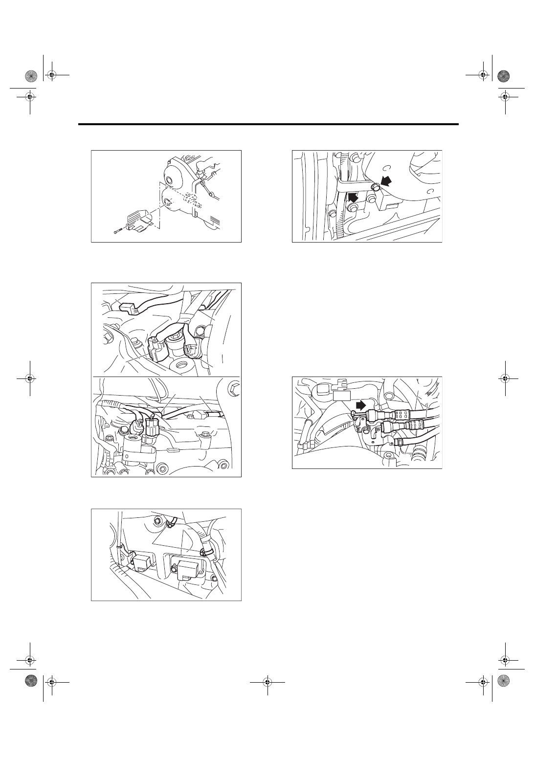
32) Remove the engine harness cover. (right side

only.)

33) Disconnect  connector  (A)  from  the  exhaust

camshaft  position  sensor,  connector  (B)  from  the

exhaust oil flow control solenoid valve, and connec-

tor (C) from the ignition coil.

34) Lower the vehicle.

35) Remove the clip (A) which hold the engine har-

ness to the rocker cover RH.

36) Remove the bolts that secure the air duct to the

rocker cover LH, and remove the engine harness.

37) Disconnect  the  fuel  delivery  hose,  fuel  return

hose and evaporation hose.
CAUTION:

• Be careful not to spill fuel.

• Catch the fuel from hoses using a container

or cloth.

(1) Set the ST to the fuel pipe.

ST 42099AE000 QUICK CONNECTOR RE-

LEASE

(2) Disconnect  the  quick  connector  of  the  fuel

delivery hose and fuel return hose by pushing

the ST in the direction of the arrow.

(3) Remove the clip and disconnect the evapo-

ration hose from the fuel pipe.

FU-03616

FU-05746

(B)

(C)

(C)

(A)

(C)

(C)

(A)

(B)

FU-03581

(A)

(A) Fuel delivery hose
(B) Fuel return hose

(C) Evaporation hose

FU-06573

ME-05008

(A)

(B)

ST

(C)

FU(STI)-21

Intake Manifold

FUEL INJECTION (FUEL SYSTEMS)

38) Remove  the  intake  manifold  from  cylinder

head.

B: INSTALLATION

1) Install the intake manifold onto cylinder heads.
NOTE:

Use a new gasket.
Tightening torque:

25 N·m (2.5 kgf-m, 18.4 ft-lb)

2) Connect the fuel delivery hose, fuel return hose,

and evaporation hose.

3) Fix the engine harness to the rocker cover LH

with the air duct.
Tightening torque:

6.4 N·m (0.7 kgf-m, 4.7 ft-lb)

4) Fix the engine harness to the rocker cover RH

with clips (A).

5) Lift up the vehicle.

FU-06574

FU-06574

(A) Fuel delivery hose
(B) Fuel return hose

(C) Evaporation hose

FU-05783

(A)

(B)

(C)

FU-06573

FU-03581

(A)

FU(STI)-22

Intake Manifold

FUEL INJECTION (FUEL SYSTEMS)

6) Connect connector (A) to the exhaust camshaft

position  sensor,  connector  (B)  to  the  exhaust  oil

flow control solenoid valve, connector (C) to the ig-

nition coil.

7) Install  the  engine  harness  cover.  (right  side

only.)
Tightening torque:

5 N·m (0.5 kgf-m, 3.7 ft-lb)

8) Lower the vehicle.

9) Connect the connector to the intake oil flow con-

trol solenoid valve.

10) Connect the connector to the intake camshaft

position sensor.

FU-05746

(B)

(C)

(C)

(A)

(C)

(C)

(A)

(B)

FU-03616

FU-03495

FU-04385

FU(STI)-23

Intake Manifold

FUEL INJECTION (FUEL SYSTEMS)

11) Connect  the  connector  to  the  secondary  air

combination valve.

12) Connect the connector to the knock sensor.

13) Connect  the  connector  to  the  power  steering

pump switch.

14) Connect the connector (A) to the engine cool-

ant  temperature  sensor,  connector  (B)  to  the  oil

pressure  switch,  and  the  connector  (C)  to  the

crankshaft position sensor.

15) Install the engine harness connector to engine

harness  bracket,  then  connect  the  bulkhead  har-

ness connector to the engine harness connector.

16) Install the engine harness to clip (A).

17) Install  the  engine  coolant  hose  to  the  water

tank pipe.

18) Connect the air control hose (A) to the waste-

gate actuator, and install the turbocharger to the in-

take duct.
Tightening torque:

3 N·m (0.3 kgf-m, 2.2 ft-lb)

FU-03493

FU-03492

FU-04598

(C)

(A)

(B)

FU-05725

FU-06571

FU-06570

(A)

FU-06569

FU-04384

(A)


Content   ..  25  26  27  28   ..